Ford Ecosport: Climate Control System
Ford Ecosport 2014-2026 Service and Repair Manual / Climate Control System
- Climate Control System - General Information
- Specifications
- Description and Operation - Climate Control System - Vehicles With: Electronic Manual Temperature Control (EMTC) - Component Location
- Description and Operation - Climate Control System - Vehicles With: Electronic Manual Temperature Control (EMTC) - Overview
- Description and Operation - Climate Control System - Vehicles With: Electronic Manual Temperature Control (EMTC) - System Operation and Component Description
- Description and Operation - Climate Control System - Vehicles With: Electronic Automatic Temperature Control (EATC) - Component Location
- Description and Operation - Climate Control System - Vehicles With: Electronic Automatic Temperature Control (EATC) - Overview
- Description and Operation - Climate Control System - Vehicles With: Electronic Automatic Temperature Control (EATC) - System Operation and Component Description
- Diagnosis and Testing - Climate Control System - Vehicles With: Electronic Automatic Temperature Control (EATC)
- General Procedures - Air Conditioning (A/C) Clutch Air Gap Adjustment
- General Procedures - Air Conditioning (A/C) Clutch and Air Conditioning (A/C) Clutch Field Coil
- General Procedures - Air Conditioning (A/C) Compressor Leak Detection - Vehicles With: R1234YF Refrigerant
- General Procedures - Air Conditioning (A/C) Odor Treatment - Vehicles With: R1234YF Refrigerant
- General Procedures - Air Conditioning (A/C) System Flushing - Vehicles With: R1234YF Refrigerant
- General Procedures - Air Conditioning (A/C) System Leak Test Using Forming Gas
- General Procedures - Air Conditioning (A/C) System Recovery, Evacuation and Charging - Vehicles With: R1234YF Refrigerant
- General Procedures - Condenser Core Leak Check - Vehicles With: R1234YF Refrigerant
- General Procedures - Electronic Leak Detection - Vehicles With: R1234YF Refrigerant
- General Procedures - Evaporator Core Leak Check - Vehicles With: R1234YF Refrigerant
- General Procedures - Fluorescent Dye Leak Detection - Vehicles With: R1234YF Refrigerant
- General Procedures - Heater Core Leak Check - Vehicles With: R1234YF Refrigerant
- General Procedures - Refrigerant Identification Testing - Vehicles With: R1234YF Refrigerant
- General Procedures - Refrigerant Oil Adding - Vehicles With: R1234YF Refrigerant
- General Procedures - Refrigerant System Tests - 2.0L Duratec-HE (129kW/175PS)
- General Procedures - Reset the Outside Air Temperature Sensor Learned Values
- Removal and Installation - Air Conditioning (A/C) Compressor - 2.0L Duratec-HE (129kW/175PS)
- Removal and Installation - Air Conditioning (A/C) Compressor Inlet Line - 2.0L Duratec-HE (129kW/175PS)
- Removal and Installation - Air Conditioning (A/C) Compressor Outlet Line - 2.0L Duratec-HE (129kW/175PS)
- Removal and Installation - Air Conditioning (A/C) Pressure Transducer
- Removal and Installation - Air Distribution Door Actuator
- Removal and Installation - Air Inlet Door Actuator
- Removal and Installation - Ambient Air Temperature Sensor
- Removal and Installation - Blower Motor
- Removal and Installation - Blower Motor Speed Control
- Removal and Installation - Cabin Air Filter
- Removal and Installation - Cabin Heater Coolant Pump - 2.0L Duratec-HE (129kW/175PS)
- Removal and Installation - Center Register Air Discharge Temperature Sensor
- Removal and Installation - Center Registers
- Removal and Installation - Climate Control Housing
- Removal and Installation - Condenser - 2.0L Duratec-HE (129kW/175PS)
- Removal and Installation - Condenser Outlet Line - 2.0L Duratec-HE (129kW/175PS)
- Removal and Installation - Driver Side Register
- Removal and Installation - Evaporator
- Removal and Installation - Evaporator Inlet and Outlet Manifold - 2.0L Duratec-HE (129kW/175PS)
- Removal and Installation - Evaporator Temperature Sensor
- Removal and Installation - Footwell Air Discharge Temperature Sensor
- Removal and Installation - Heater Core
- Removal and Installation - Heating, Ventilation and Air Conditioning (HVAC) Control Module
- Removal and Installation - In-Vehicle Temperature Sensor
- Removal and Installation - Passenger Side Register
- Removal and Installation - Receiver Drier Element
- Removal and Installation - Sunload Sensor
- Removal and Installation - Temperature Door Actuator
- Removal and Installation - Thermostatic Expansion Valve
- Supplemental Climate Control
 Diagnosis and Testing - Speed Control
Refer to Wiring Diagrams Section 310-03 for schematic and connector information.
General Equipment
Ford diagnostic equipment
Inspection and Verification
Verify the customer concern by operating the system...

Other information:
Ford Ecosport 2014-2026 Service and Repair Manual: Removal and Installation - Rear Shock Absorber
Special Tool(s) / General Equipment Transmission Jack Vehicle/Axle Stands Removal NOTICE: Suspension fasteners are critical parts that affect the performance of vital components and systems. Failure of these fasteners may result in major service expense. Use the same or equivalent parts if replacement is necessary. Do not use a replacement part of lesser ..
Ford Ecosport 2014-2026 Service and Repair Manual: Removal and Installation - Rear Door
Special Tool(s) / General Equipment Door Lift Removal NOTE: Removal steps in this procedure may contain installation details. NOTE: LH side shown, RH side similar. Open the rear door. Remove the check arm bolt. Torque: 17 lb.ft (23 Nm) ..
Categories
- Manuals Home
- 2nd Gen Ford Ecosport Service Manual (2014 - 2026)
- Description and Operation - Evaporative Emissions - System Operation and Component Description
- Removal and Installation - Fuel Pump and Sender Unit
- General Procedures - Battery Charging
- Body and Paint
- Removal and Installation - Roof Rail
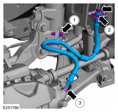
Removal and Installation - Front Brake Flexible Hose
Removal
Remove the wheel and tire.Refer to: Wheel and Tire (204-04A Wheels and Tires, Removal and Installation).
Remove the brake flexible hose bracket bolt.
Disconnect the brake tube fitting and remove the brake hose clip.
Loosen the brake hose fitting and remove the brake flexible hose.
Copyright © 2026 www.foecosport2.com