Ford Ecosport: Starting System - 2.0L Duratec-HE (129kW/175PS) / Removal and Installation - Starter Motor
Ford Ecosport 2014-2026 Service and Repair Manual / Engine / Starting System - 2.0L Duratec-HE (129kW/175PS) / Removal and Installation - Starter Motor
Removal
NOTE: Removal steps in this procedure may contain installation details.
-
 WARNING:
Before beginning any service procedure, refer to
health and safety warnings in section 100-00 General Information within
workshop manual. Failure to follow this instruction may result in
serious personal injury.
WARNING:
Before beginning any service procedure, refer to
health and safety warnings in section 100-00 General Information within
workshop manual. Failure to follow this instruction may result in
serious personal injury.
Refer to: Health and Safety Precautions (100-00 General Information, Description and Operation).
-
Disconnect the battery.
Refer to: Battery Disconnect and Connect (414-01 Battery, Mounting and Cables, General Procedures).
-
With the vehicle in NEUTRAL, position it on a hoist.
Refer to: Jacking and Lifting - Overview (100-02 Jacking and Lifting, Description and Operation).
-
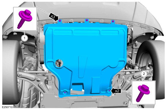
Remove the retainers and the underbody shield.
Torque:
1: 13 lb.in (1.5 Nm)
2: 22 lb.in (2.5 Nm)
 |
-
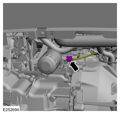
Disconnect the oil pressure switch electrical connector.
 |
-
-
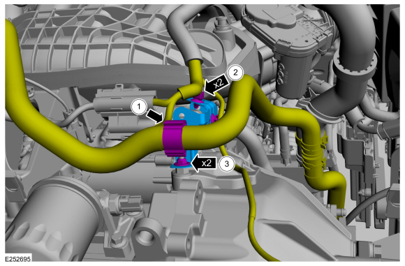
Detach the wiring harness retainer and position the wiring harness aside.
-
Detach the wiring harness retainers and position the wiring harness aside.
-
Remove the starter motor bracket nuts and then remove the starter motor bracket.
Torque: 44 lb.in (5 Nm)
-
Detach the wiring harness retainer and position the wiring harness aside.
 |
-
-
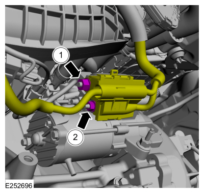
Remove the starter motor solenoid control wire
retaining nut and then disconnect the starter motor solenoid control
wire.
Torque: 106 lb.in (12 Nm)
-
Remove the starter motor solenoid positive battery
cable retaining nut and then disconnect the starter motor solenoid
battery cable.
Torque: 53 lb.in (6 Nm)
-
Remove the starter motor solenoid control wire
retaining nut and then disconnect the starter motor solenoid control
wire.
 |
-
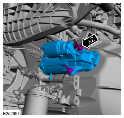
Remove the starter motor retaining bolts and then remove the starter motor.
Torque: 26 lb.ft (35 Nm)
 |
Installation
-
Inspect the starter motor drive gear and ring gear.
Refer to: Starter Motor Drive Gear and Flywheel Ring Gear Inspection (303-06C Starting System - 2.0L Duratec-HE (129kW/175PS), General Procedures).
-
To install, reverse the removal procedure.
 General Procedures - Starter Motor Drive Gear and Flywheel Ring Gear Inspection
Activation
WARNING:
Before beginning any service procedure in this
section, refer to Safety Warnings in section 100-00 General Information...
 Removal and Installation - Start Inhibit Switch
Removal
NOTICE:
Make sure that the clutch pedal remains in the rest position.
NOTE:
Removal steps in this procedure may contain installation details...
Other information:
Ford Ecosport 2014-2026 Service and Repair Manual: Description and Operation - Information and Entertainment System - Overview
Overview Audio System NOTE: Refer to the Owner Literature for additional details of the audio system. AM / FM /Satellite Radio The ACM can operate when the ignition is on or off. The accessory delay feature powers the audio system, after the ignition has been turned off, for a preset time or until a front door is opened...
Ford Ecosport 2014-2026 Service and Repair Manual: Description and Operation - Rear Suspension - Component Location
Item Description 1 Shock absorber 2 Spring 3 Twist-beam rear axle 4 Rear axle bushing ..
Categories
- Manuals Home
- 2nd Gen Ford Ecosport Service Manual (2014 - 2026)
- Removal and Installation - Catalytic Converter
- Removal and Installation - Body Control Module (BCM)
- Engine
- Body and Paint
- Removal and Installation - Blower Motor
Removal and Installation - Steering Column Shaft
Removal
NOTE: Removal steps in this procedure may contain installation details.
NOTICE: Do not allow the steering column to rotate while the steering column shaft is disconnected or damage to the steering column internal sensor may result.
NOTE: Use a steering wheel holding device (such as Hunter® 28-75-1 or equivalent)
Hold the steering wheel in the straight-ahead position.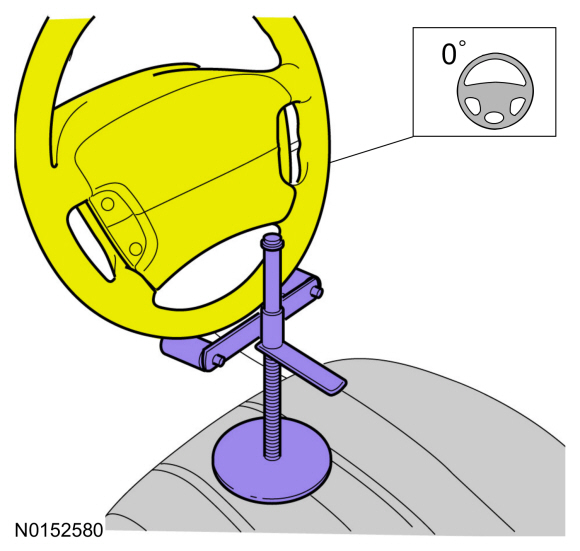
Copyright © 2026 www.foecosport2.com