Ford Ecosport: Speed Control / Diagnosis and Testing - Speed Control
Ford Ecosport 2014-2026 Service and Repair Manual / Fuel System / Speed Control / Diagnosis and Testing - Speed Control
Refer to Wiring Diagrams Section 310-03 for schematic and connector information.
General Equipment
| Ford diagnostic equipment |
Inspection and Verification
-
Verify the customer concern by operating the system.
-
Visually inspect for obvious signs of mechanical or electrical damage.
Visual Inspection Chart
| Mechanical | Electrical |
|---|---|
|
|
-
If an obvious cause for an observed or reported concern is
found, correct the cause (if possible) before proceeding to the next
step.
-
If the cause is not visually evident, verify the symptom and
refer to the diagnostic tab within the Ford diagnostic equipment.
 Description and Operation - Speed Control - System Operation and Component Description
System Diagram
Item
Description
1
Control switch unit - cruise control system
2
Clockspring
3
Instrument cluster
4
wheel speed sensor,
5
ABS module
6
TCM
Comments:Vehicles with automatic transaxle...

Other information:
Ford Ecosport 2014-2026 Service and Repair Manual: General Procedures - Selector Lever Cable Adjustment - 6-Speed Automatic Transmission – 6F15
Adjustment Apply the parking brake. Position the selector lever in D . If equipped with a 1.5L engine, remove the air filter. Refer to: Air Cleaner (303-12B Intake Air Distribution and Filtering - 1.5L Duratec (90kW/120PS) – I3, Removal and Installation). D..
Ford Ecosport 2014-2026 Service and Repair Manual: Diagnosis and Testing - Tire Pressure Monitoring System (TPMS)
DTC Charts Diagnostics in this manual assume a certain skill level and knowledge of Ford-specific diagnostic practices. REFER to: Diagnostic Methods (100-00 General Information, Description and Operation). BCM DTC Chart DTC Description Action B1182:00 Tire Pressure Monitor..
Categories
- Manuals Home
- 2nd Gen Ford Ecosport Service Manual (2014 - 2026)
- Diagnosis and Testing - Body Control Module (BCM)
- Description and Operation - Evaporative Emissions - System Operation and Component Description
- Removal and Installation - Fuel Pump and Sender Unit
- Removal and Installation - Blower Motor
- Removal and Installation - Roof Rail
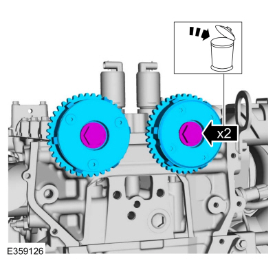
Removal and Installation - Variable Camshaft Timing (VCT) Unit
Removal
NOTICE: During engine repair procedures, cleanliness is extremely important. Any foreign material, including any material created while cleaning gasket surfaces, that enters the oil passages, coolant passages or the oil pan can cause engine failure.
Remove the timing chain.Refer to: Timing Chain (303-01C Engine - 2.0L Duratec-HE (129kW/175PS), Removal and Installation).
Remove the bolts and VCT units.
Discard the bolts.
Copyright © 2026 www.foecosport2.com