Ford Ecosport: Engine Cooling - 2.0L Duratec-HE (129kW/175PS) / Removal and Installation - Coolant Pump
Ford Ecosport 2014-2026 Service and Repair Manual / Engine / Engine Cooling - 2.0L Duratec-HE (129kW/175PS) / Removal and Installation - Coolant Pump
Materials
| Name | Specification |
|---|---|
| Motorcraft® Orange Prediluted Antifreeze/Coolant VC-3DIL-B |
WSS-M97B44-D2 |
| Motorcraft® Orange Concentrated Antifreeze/Coolant VC-3-B |
WSS-M97B44-D |
Removal
-
Drain the cooling system.
Refer to: Engine Cooling System Draining, Vacuum Filling and Bleeding (303-03C Engine Cooling - 2.0L Duratec-HE (129kW/175PS), General Procedures).
-
Remove the RH headlamp.
-
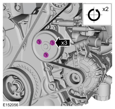
Loosen the coolant pump pulley bolts.
 |
-
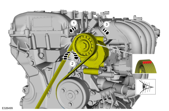
NOTE: Make sure the accessory drive belt is positioned so coolant can not contaminate the belt.
-
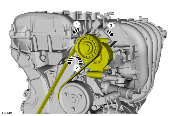
Rotate the accessory drive belt tensioner.
-
Position aside the accessory drive belt.
-
Release the accessory drive belt tensioner.
-
Rotate the accessory drive belt tensioner.
 |
-
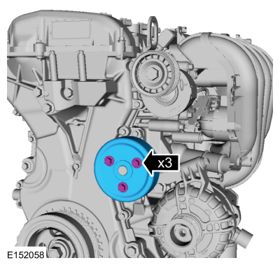
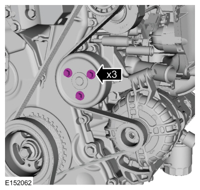
Remove the bolts and the coolant pump pulley.
 |
-
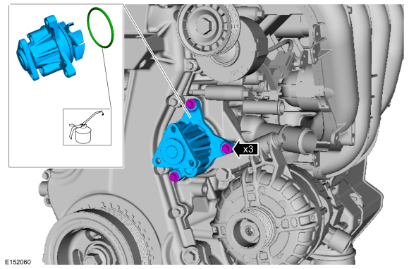
Remove the bolts and the coolant pump. Discard the O-ring seal.
 |
Installation
-
Lubricate the O-ring seal with clean engine coolant. Install the coolant pump and the bolts.
Material: Motorcraft® Orange Concentrated Antifreeze/Coolant / VC-3-B (WSS-M97B44-D)
Material: Motorcraft® Orange Prediluted Antifreeze/Coolant / VC-3DIL-B (WSS-M97B44-D2)
Torque: 89 lb.in (10 Nm)
 |
-
NOTE: Only tighten the bolts finger tight at this time.
Position the coolant pump pulley and install the bolts finger tight.
|
-
-
Rotate the accessory drive belt tensioner.
-
Position the accessory drive belt.
-
Release the accessory drive belt tensioner.
-
Rotate the accessory drive belt tensioner.
 |
-
Tighten the coolant pump pulley bolts.
Torque: 177 lb.in (20 Nm)
 |
-
Install the RH headlamp.
-
Fill and bleed the cooling system.
Refer to: Engine Cooling System Draining, Vacuum Filling and Bleeding (303-03C Engine Cooling - 2.0L Duratec-HE (129kW/175PS), General Procedures).
 Removal and Installation - Block Heater
Removal
NOTE:
Removal steps in this procedure may contain installation details.
WARNING:
Before beginning any service procedure in this
section, refer to Safety Warnings in section 100-00 General Information...
 Removal and Installation - Cooling Fan Motor and Shroud
Special Tool(s) /
General Equipment
Hose Clamp Remover/Installer
Removal
NOTE:
Removal steps in this procedure may contain installation details...
Other information:
Ford Ecosport 2014-2026 Service and Repair Manual: Removal and Installation - Blower Motor Speed Control
Special Tool(s) / General Equipment Interior Trim Remover Removal NOTE: Removal steps in this procedure may contain installation details. Vehicles with automatic transmission Remove the selector lever trim panel...
Ford Ecosport 2014-2026 Service and Repair Manual: Removal and Installation - Rear Seatbelt Buckle LH
Removal NOTE: Removal steps in this procedure may contain installation details. Position the rear seat cushion to the full forward position. Remove the bolt and position the rear LH seatbelt buckle aside...
Categories
- Manuals Home
- 2nd Gen Ford Ecosport Service Manual (2014 - 2026)
- Engine
- General Procedures - Battery Charging
- Description and Operation - Jacking and Lifting - Overview
- Service Information
- General Procedures - Transmission Fluid Level Check
Removal and Installation - Wheel Knuckle Bushing
Special Tool(s) / General Equipment
Hydraulic PressRemoval
NOTE: Removal steps in this procedure may contain installation details.
Remove the wheel knuckle.Refer to: Wheel Knuckle - Vehicles With: Rear Drum Brakes (204-02B Rear Suspension - AWD, Removal and Installation).
Remove the rear toe adjustment retainers and remove the wheel knuckle mounting bracket.
Torque:
Stage 1: 177 lb.in (20 Nm)
Stage 2: 76 lb.ft (103 Nm)
Copyright © 2026 www.foecosport2.com