Ford Ecosport: Engine Cooling - 2.0L Duratec-HE (129kW/175PS) / Removal and Installation - Cooling Fan Motor and Shroud
Ford Ecosport 2014-2025 Service and Repair Manual / Engine / Engine Cooling - 2.0L Duratec-HE (129kW/175PS) / Removal and Installation - Cooling Fan Motor and Shroud
Special Tool(s) / General Equipment
| Hose Clamp Remover/Installer |
Removal
NOTE: Removal steps in this procedure may contain installation details.
-
With the vehicle in NEUTRAL, position it on a hoist.
Refer to: Jacking and Lifting - Overview (100-02 Jacking and Lifting, Description and Operation).
-
Drain the cooling system.
Refer to: Engine Cooling System Draining, Vacuum Filling and Bleeding (303-03C Engine Cooling - 2.0L Duratec-HE (129kW/175PS), General Procedures).
-
Remove the air cleaner.
Refer to: Air Cleaner (303-12C Intake Air Distribution and Filtering - 2.0L Duratec-HE (129kW/175PS), Removal and Installation).
-
Remove the LH headlamp.
Refer to: Headlamp Assembly (417-01 Exterior Lighting, Removal and Installation).
-
Depress the tabs and disconnect the coolant tube.
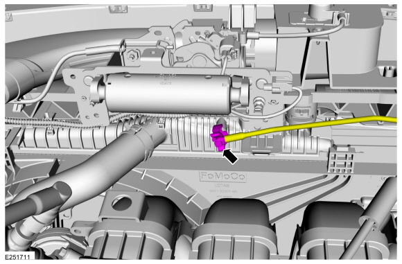 |
-
Remove the retainers and the damper.
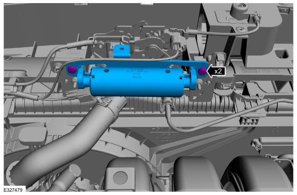 |
-
-
Disconnect the cooling fan motor electrical connectors and detach the wire harness retainers.
-
Detach the lower radiator hose retainer.
-
Disconnect the cooling fan motor electrical connectors and detach the wire harness retainers.
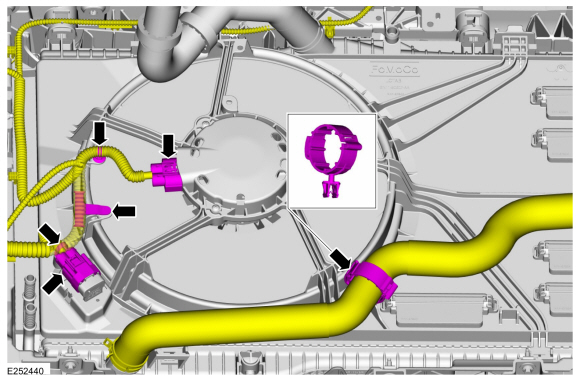 |
-
-
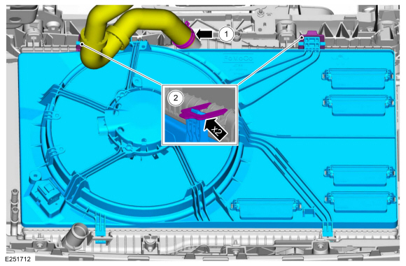
Release the clamp and disconnect the upper radiator hose.
Use the General Equipment: Hose Clamp Remover/Installer
-
Release the tabs and remove the cooling fan motor and shroud assembly.
-
Release the clamp and disconnect the upper radiator hose.
 |
Installation
-
To install, reverse the removal procedure.
-
Fill and bleed the cooling system.
Refer to: Engine Cooling System Draining, Vacuum Filling and Bleeding (303-03C Engine Cooling - 2.0L Duratec-HE (129kW/175PS), General Procedures).
 Removal and Installation - Coolant Pump
Materials
Name
Specification
Motorcraft® Orange Prediluted Antifreeze/CoolantVC-3DIL-B
WSS-M97B44-D2
Motorcraft® Orange Concentrated Antifreeze/CoolantVC-3-B
WSS-M97B44-D
Removal
Drain the cooling system...
 Removal and Installation - Degas Bottle
Special Tool(s) /
General Equipment
Fluid Suction Gun
Hose Clamp Remover/Installer
Locking Pliers
Materials
Name
Specification
Motorcraft® Orange Prediluted Antifreeze/CoolantVC-3DIL-B
WSS-M97B44-D2
Removal
WARNING:
Always allow the engine to cool before opening the cooling
system...
Other information:
Ford Ecosport 2014-2025 Service and Repair Manual: Removal and Installation - Active Grille Shutter Actuator
Removal NOTE: Removal steps in this procedure may contain installation details. Remove the active grill shutter. Refer to: Active Grille Shutter - 2.0L Duratec-HE (125kW/170PS) – MI4 (501-02 Front End Body Panels, Removal and Installation)...
Ford Ecosport 2014-2025 Service and Repair Manual: Removal and Installation - Ignition Coil-On-Plug
Removal NOTE: Removal steps in this procedure may contain installation details. Remove the engine appearance cover. Using compressed air, remove any foreign material from the ignition coil-on-plugs and surrounding area...
Categories
- Manuals Home
- 2nd Gen Ford Ecosport Service Manual (2014 - 2025)
- Engine
- Diagnosis and Testing - Evaporative Emissions
- Service Information
- Description and Operation - Evaporative Emissions - System Operation and Component Description
- Removal and Installation - Blower Motor
Removal and Installation - Rear Halfshaft Seal
Special Tool(s) / General Equipment
 205-153
(T80T-4000-W)
205-153
(T80T-4000-W)
Handle
 205-990
Installer, Axle Seal
TKIT-2012A-FL
TKIT-2012A-ROW
Copyright © 2025 www.foecosport2.com