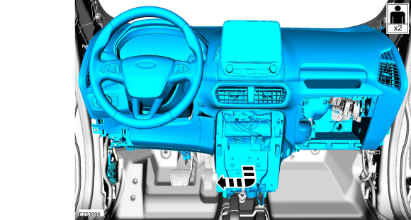
Ford Ecosport: Instrument Panel and Console / Removal and Installation - Instrument Panel
Special Tool(s) /
General Equipment
Removal
NOTE:
Removal steps in this procedure may contain installation details.
NOTE:
During the removal or installation of components, cap, tape
or otherwise appropriately protect all openings and tubes/fittings to
prevent the ingress of dirt or other contamination. Remove caps, tape
and other protective materials prior to installation.
All vehicles
-
Evacuate the A/C system.
Refer to: Air Conditioning (A/C) System Recovery, Evacuation and
Charging - Vehicles With: R134A Refrigerant (412-00 Climate Control
System - General Information, General Procedures).
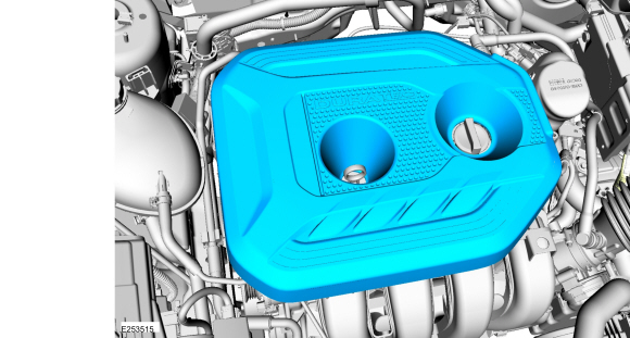
1.5L/2.0L
-
Remove the engine appearance cover.
1.5L
-
Remove the engine appearance cover.
All vehicles
-
Remove the cowl panel grille.
Refer to: Cowl Panel Grille (501-02 Front End Body Panels, Removal and Installation).
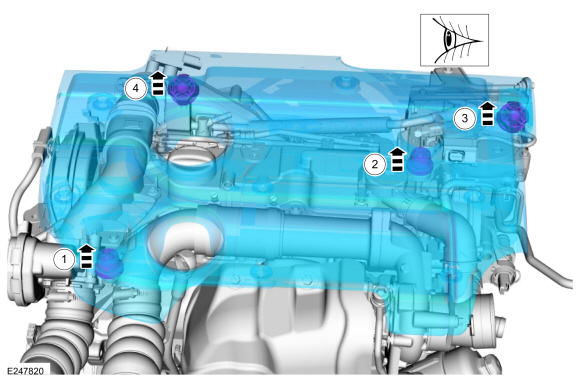
-
Remove the cowl panel bolts, position aside the vacuum line and remove the cowl panel.
-
Remove the bolts.
Torque:
27 lb.in (3 Nm)
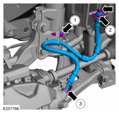
-
Remove the bolts.
Torque:
44 lb.in (5 Nm)
-
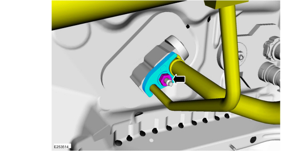
Remove the thermostatic expansion valve nut and flange, and position aside the lines.
-
Make sure to cover any open ports to prevent debris from entering the system.
Torque:
133 lb.in (15 Nm)
-
Lubricate the refrigernat system with the
correct amount of clean PAG oil. Refer to the appropriate Refrigerant
Oil Adding procedure in Group 412.
-
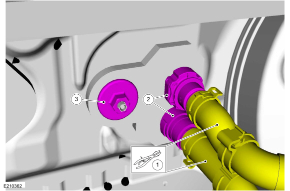
-
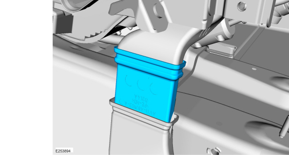
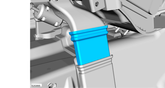
Pinch off the heater hoses.
Use the General Equipment: Locking Pliers
-
Disconnect the heater hoses.
-
Remove the HVAC nut.
Torque:
9 lb.in (1 Nm)
-
Make sure to cover any open ports to prevent
coolant from spilling into the interior while removing the instrument
panel from the vehicle.
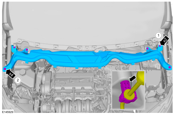
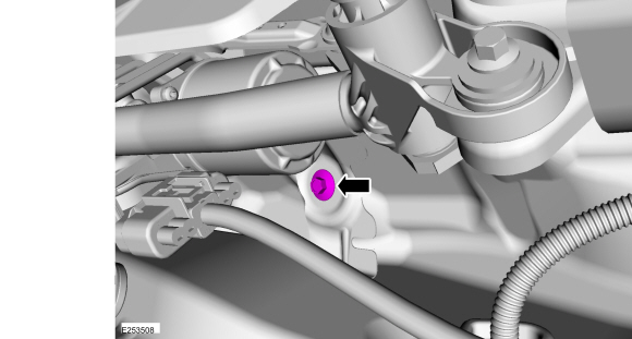
-
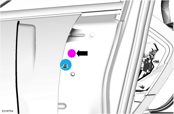
Remove the cowl to in-vehicle cross beam bolt.
Torque:
22 lb.ft (30 Nm)
-
Remove the floor console.
Refer to: Floor Console (501-12 Instrument Panel and Console, Removal and Installation).
-
Remove the A-pillar trim panels.
Refer to: A-Pillar Trim Panel (501-05 Interior Trim and Ornamentation, Removal and Installation).
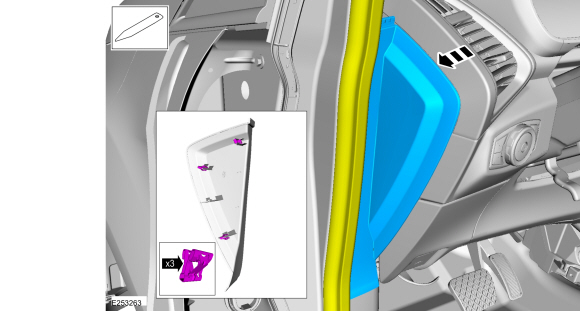
-
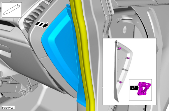
Position aside the weather strip, release the clips and remove the LH instrument panel side trim panel.
-
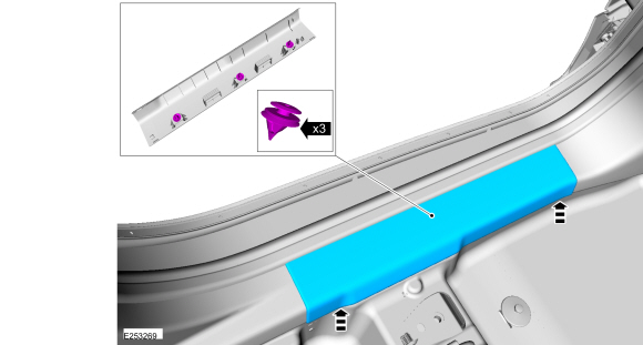
Release the retainers and remove the LH scuff plate.
-
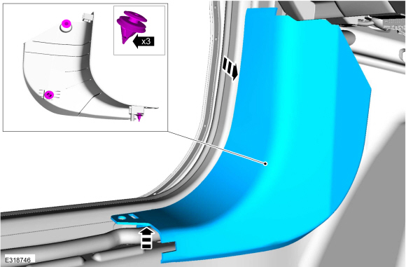
Release the retainers and remove the LH lower cowl trim panel.
-
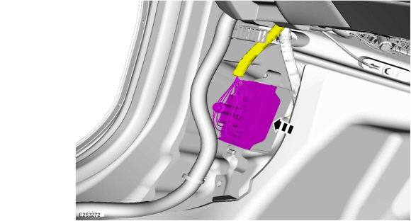
Disconnect the electrical connector.
-
Remove the hood release handle.
Refer to: Hood Latch Release Handle (501-14 Handles, Locks, Latches and Entry Systems, Removal and Installation).
-
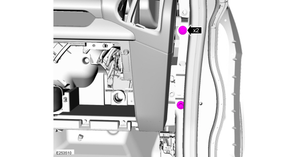
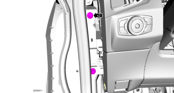
Position aside the weather strip, release the clips and remove the RH instrument panel side trim panel.
-
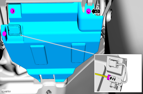
Remove the bolts and the RH hush panel.
-
Disconnect the electrical connector.
-
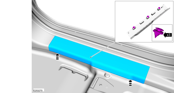
Release the retainers and remove the RH scuff plate.
-
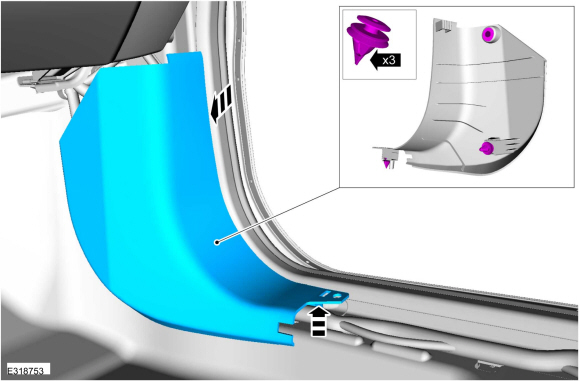
Release the retainers and remove the RH lower cowl trim panel.
-
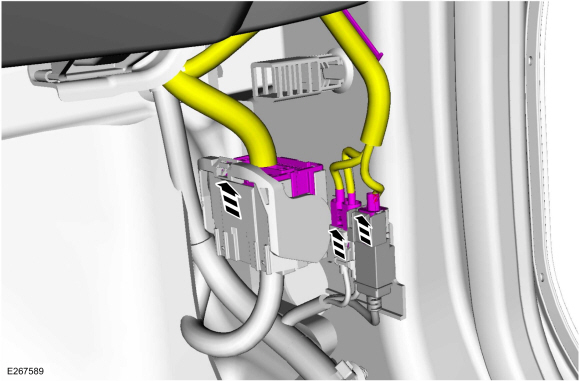
Disconnect the electrical connectors.
-
Remove the driver side front door only.
Refer to: Front Door (501-03 Body Closures, Removal and Installation).
-
NOTE:
Driver side door opening, upper cowl.
Remove the bolt cover and the LH upper cowl on in-vehicle cross beam bolt.
Torque:
18 lb.ft (25 Nm)
-
NOTE:
Do not allow the steering wheel to rotate while
the steering column shaft is disconnected or damage to the clockspring
may result.
Secure the steering column.
-
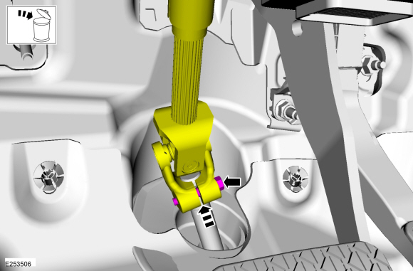
 WARNING:
Do not reuse steering column shaft bolts. This
may result in fastener failure and steering column shaft detachment or
loss of steering control. Failure to follow this instruction may result
in serious injury to vehicle occupant(s).
WARNING:
Do not reuse steering column shaft bolts. This
may result in fastener failure and steering column shaft detachment or
loss of steering control. Failure to follow this instruction may result
in serious injury to vehicle occupant(s).
NOTICE:
Remove and discard the lower steering column shaft
coupler bolt and separate the steering column shaft coupler from the
steering shaft.
Torque:
25 lb.ft (34 Nm)
-
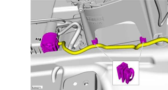
Disconnect the electrical connector, release the harness retainers and position aisde the harness.
Vehicles with automatic transmission
-
-
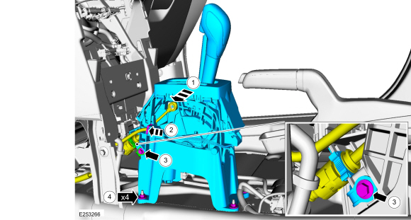
Remove the selector lever cable end from the selector lever mechanism.
-
Disconnect the electrical connector.
-
Remove the selector lever cable retaining clip bolt and remove the clip from the selector lever cable.
-
Remove the nuts and the selector lever assembly.
Torque:
80 lb.in (9 Nm)
All vehicles
-
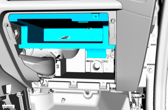
Remove the glove compartment.
Refer to: Glove Compartment (501-12 Instrument Panel and Console, Removal and Installation).
-
Remove the glove compartment tray.
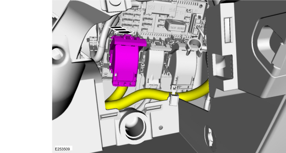
-
Disconnect the electrical connector.
-
Remove the bolts and the RH side instrument panel center support brace.
Torque:
18 lb.ft (25 Nm)
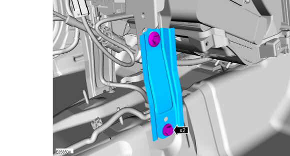
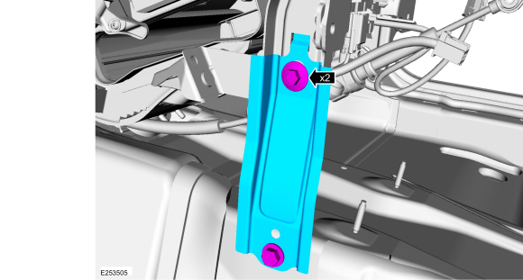
-
Remove the bolts and the LH side instrument panel center support brace.
Torque:
18 lb.ft (25 Nm)
-
NOTE:
If equipped.
Remove the LH
HVAC duct.
-
NOTE:
If equipped.
Remove the RH
HVAC duct.
-
Remove the RH instrument panel bolts.
Torque:
18 lb.ft (25 Nm)
-
Remove the LH instrument panel bolts.
Torque:
18 lb.ft (25 Nm)
-
NOTE:
To avoid damaging the instrument panel, an assistant is required when carrying out this step.
NOTE:
Make sure not to damage the instrument panel when removing the instrument panel from the vehicle.
NOTE:
Make sure that all electrical connectors and
wiring are not hindered before removing the instrument panel or damage
to the components may occur.
Remove the instrument panel through the drivers side door opening.
Installation
-
To install, reverse the removal procedure.
-
Fill and bleed the cooling system. Refer to the correct
filling and bleeding without a vacuum cooling system filler procedure in
group 303-03.
Removal
Open the glove compartment.
Release the golve compartment stops and remove the dampener...
Removal
NOTE:
Removal steps in this procedure may contain installation details.
Remove the instrument panel.
Refer to: Instrument Panel (501-12 Instrument Panel and Console, Removal and Installation)...
Other information:
Adjustment
NOTE:
The front sliding glass panel initialization procedure must
be done when repairs are carried out on the roof opening panel system,
including: any time the roof opening panel motor has been removed, the
roof opening panel glass has been removed or adjusted, or if the roof
opening panel frame has been removed...
B140B:11, B140B:12, B140B:13, B140B:1A
Refer to Wiring Diagrams Cell 46 for schematic and connector information.
Normal Operation and Fault Conditions
The RCM continuously monitors the passenger second row side airbag circuits for the following faults:
Resistance out of range
Unexpected voltage
Short to ground
Faulted passenger second row side air..
 Removal and Installation - Glove Compartment
 Removal and Installation - Instrument Panel Upper Section