Ford Ecosport: Instrument Panel and Console / Removal and Installation - Instrument Panel Upper Section
Ford Ecosport 2014-2026 Service and Repair Manual / Body and Paint / Instrument Panel and Console / Removal and Installation - Instrument Panel Upper Section
Removal
NOTE: Removal steps in this procedure may contain installation details.
-
Remove the instrument panel.
Refer to: Instrument Panel (501-12 Instrument Panel and Console, Removal and Installation).
-
Remove the ACM .
Refer to: Audio Front Control Module (ACM) (415-00 Information and Entertainment System - General Information, Removal and Installation).
-
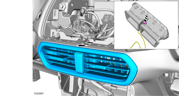
Remove the instrument panel center register.
-
Disconnect the electrical connector.
-
Disconnect the electrical connector.
 |
-
Remove the headlamp switch.
Refer to: Headlamp Switch (417-01 Exterior Lighting, Removal and Installation).
-
Remove the IPC
Refer to: Instrument Panel Cluster (IPC) (413-01 Instrumentation, Message Center and Warning Chimes, Removal and Installation).
-
Remove the steering column.
Refer to: Steering Column - LHD (211-04 Steering Column, Removal and Installation).
-
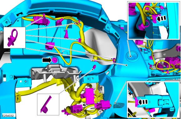
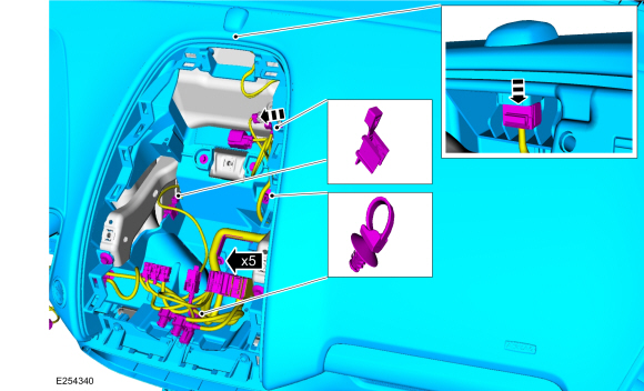
Remove the bolt in the IPC opening.
-
Disconnect the electrical connectors, release the
electrical harness retainers and position aside the electrical harness.
Torque: 44 lb.in (5 Nm)
-
Disconnect the electrical connectors, release the
electrical harness retainers and position aside the electrical harness.
 |
-
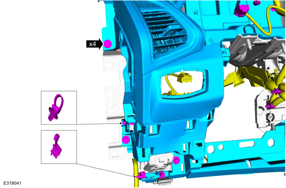
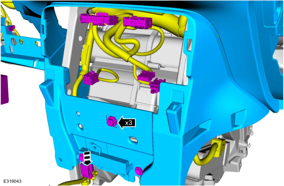
Remove the bolts on the drivers side of the instrument panel.
-
Release the electrical harness retainers and position aside the electrical harness.
Torque: 44 lb.in (5 Nm)
-
Release the electrical harness retainers and position aside the electrical harness.
 |
-
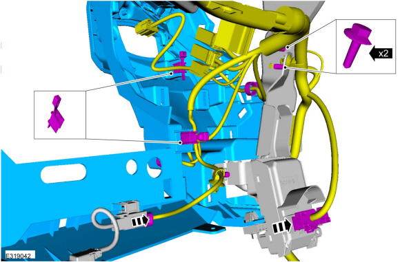
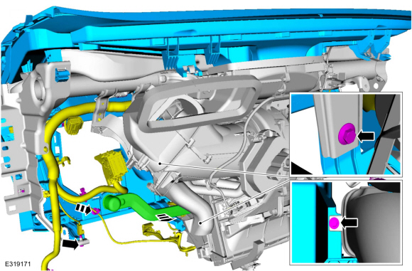
At the drivers side rear of the instrument panel,
disconnect the electrical connectors, release the electrical harness
retainers disconnect the ground bolts and position aside the electrical
harness.
 |
-
Remove the GWM .
Refer to: Gateway Module A (GWM) (418-00 Module Communications Network, Removal and Installation).
-
Remove the bolts in the lower center of the instrument panel opening.
-
Disconnect the electrical connectors, release the
electrical harness retainers and position aside the electrical harness.
Torque: 44 lb.in (5 Nm)
-
Disconnect the electrical connectors, release the
electrical harness retainers and position aside the electrical harness.
 |
-
Remove the bolt in the lower center of the instrument panel.
-
Disconnect the electrical connector and position aside the electrical harness.
Torque: 44 lb.in (5 Nm)
-
Disconnect the electrical connector and position aside the electrical harness.
 |
-
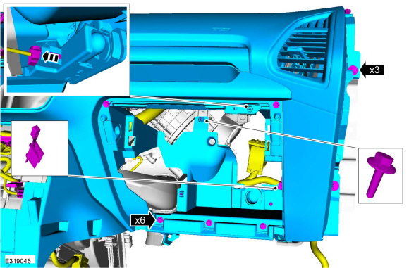
Remove the bolts on the passenger side of the instrument panel.
-
Disconnect the electrical connector, release the
electrical harness retainer and position aside the electrical harness.
Torque: 44 lb.in (5 Nm)
-
Disconnect the electrical connector, release the
electrical harness retainer and position aside the electrical harness.
 |
-
Remove the bolts at the passenger side rear of the instrument panel.
-
Remove the glove box ventilation tube from the
instrument panel upper section and the climate control housing.
-
Disconnect the electrical connectors, release the
electrical harness retainers and position aside the electrical harness.
Torque: 44 lb.in (5 Nm)
-
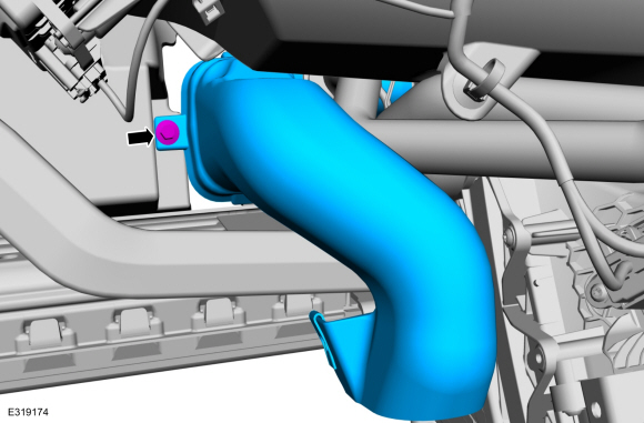
Remove the glove box ventilation tube from the
instrument panel upper section and the climate control housing.
 |
-
Remove the bolt and the RH floor duct.
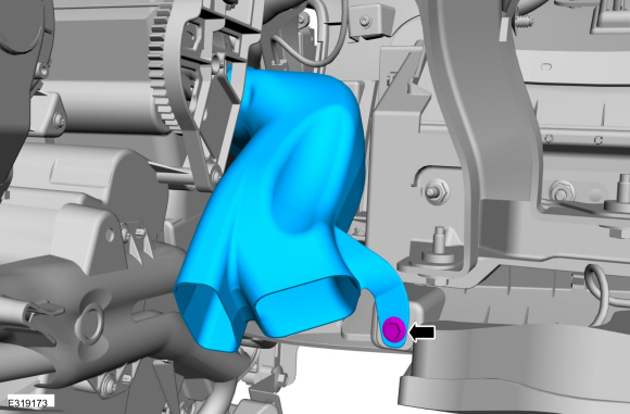 |
-
Remove the bolt and allow the LH floor duct remain loose until the instrument panel upper section is removed. .
 |
-
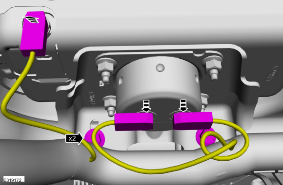
Remove the passenger side airbag bolts.
-
Disconnect the electrical connectors.
Torque: 22 lb.in (2.5 Nm)
-
Disconnect the electrical connectors.
 |
-
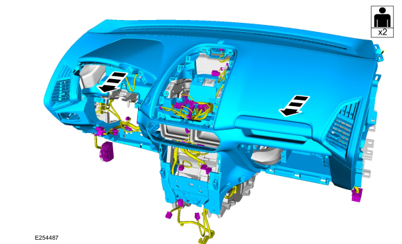
NOTE: Make sure that all electrical connectors and wiring are not hindered before removing the instrument panel upper section or damage to the components may occur.
Remove the instrument panel upper section from the in-vehicle cross beam.
 |
Installation
-
To insall, reverse the removal procedure.
 Removal and Installation - Instrument Panel
Special Tool(s) /
General Equipment
Locking Pliers
Removal
NOTE:
Removal steps in this procedure may contain installation details...
 Removal and Installation - Overhead Console
Special Tool(s) /
General Equipment
Interior Trim Remover
Removal
Remove the switch panel.
Disconnect the electrical connectors...
Other information:
Ford Ecosport 2014-2026 Service and Repair Manual: Removal and Installation - Cooling Fan Motor and Shroud
Special Tool(s) / General Equipment Hose Clamp Remover/Installer Removal NOTE: Removal steps in this procedure may contain installation details. With the vehicle in NEUTRAL, position it on a hoist. Refer to: Jacking and Lifting - Overview (100-02 Jacking and Lifting, Description and Operation)...
Ford Ecosport 2014-2026 Service and Repair Manual: Removal and Installation - Cellular Phone Antenna Cable
Removal NOTE: Removal steps in this procedure may contain installation details. NOTE: The original equipment cellular phone antenna cable is part of the wiring harness and cannot be removed. This procedure refers to replacement of the cable only by overlaying the cable...
Categories
- Manuals Home
- 2nd Gen Ford Ecosport Service Manual (2014 - 2026)
- Removal and Installation - Blower Motor
- Removal and Installation - Catalytic Converter
- Removal and Installation - Fuel Pump and Sender Unit
- General Procedures - Battery Charging
- Engine
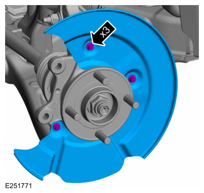
Removal and Installation - Brake Disc Shield
Removal
NOTE: Removal steps in this procedure may contain installation details.
Remove the brake disc.Refer to: Brake Disc (206-03 Front Disc Brake, Removal and Installation).
Remove the bolts and brake disc.
Torque: 80 lb.in (9 Nm)
Copyright © 2026 www.foecosport2.com