Ford Ecosport: Interior Trim and Ornamentation / Removal and Installation - C-Pillar Lower Trim Panel
Ford Ecosport 2014-2026 Service and Repair Manual / Body and Paint / Interior Trim and Ornamentation / Removal and Installation - C-Pillar Lower Trim Panel
Removal
NOTE: RH shown, LH similar.
-
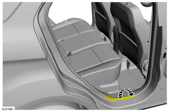
Position the rear door weatherstrip aside.
 |
-
Release the clips and remove the rear door scuff plate trim panel.
 |
-
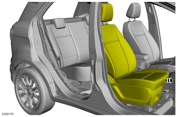
Position the front seat in the full forward position.
 |
-
Position the rear seat in the full fold flat position.
-
Position the rear seat cushion in the full forward position.
-
Position the rear seat backrest in the full flat position.
-
Position the rear seat cushion in the full forward position.
 |
-
Position the rear door weatherstrip aside.
 |
-
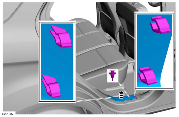
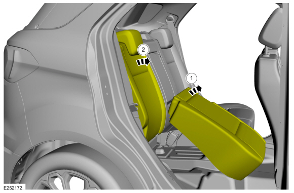
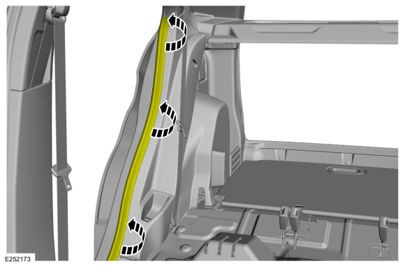
Remove the C-pillar lower trim panel.
-
Release the clips and the locator pins.
-
If equipped.
Disconnect the power-point electrical connector.
-
Release the clips and the locator pins.
 |
Installation
-
To install, reverse the removal procedure.
 Removal and Installation - B-Pillar Trim Panel
Removal
NOTE:
RH shown, LH similar.
NOTE:
Removal steps in this procedure may contain installation details.
Upper and Lower B-Pillar Trim Panels
Position the front door weatherstrip aside...
 Removal and Installation - D-Pillar Trim Panel
Removal
NOTE:
RH shown, LH similar.
NOTE:
Removal steps in this procedure may contain installation details.
Remove the C-pillar lower trim panel...
Other information:
Ford Ecosport 2014-2026 Service and Repair Manual: General Procedures - Transmission Fluid Drain and Refill
Materials Name Specification Motorcraft® MERCON® LV Automatic Transmission FluidXT-10-QLVC WSS-M2C938-AMERCON® LV, Draining With the vehicle in NEUTRAL, position it on a hoist. Refer to: Jacking and Lifting - Overview (100-02 Jacking and Lifting, Description and Operation)...
Ford Ecosport 2014-2026 Service and Repair Manual: Removal and Installation - Front Impact Severity Sensor
Removal WARNING: The following procedure prescribes critical repair steps required for correct restraint system operation during a crash. Follow all notes and steps carefully. Failure to follow step instructions may result in incorrect operation of the restraint system and increases the risk of serious personal injury or death in a crash...
Categories
- Manuals Home
- 2nd Gen Ford Ecosport Service Manual (2014 - 2026)
- General Procedures - Battery Charging
- Description and Operation - Evaporative Emissions - System Operation and Component Description
- Engine
- Removal and Installation - Fuel Pump and Sender Unit
- Removal and Installation - Front Seat
Removal and Installation - Oil Pressure Switch
Materials
Name Specification Motorcraft® Thread Sealant with PTFETA-24-B WSK-M2G350-A2
Removal
NOTE: Removal steps in this procedure may contain installation details.
With the vehicle in NEUTRAL, position it on a hoist.Refer to: Jacking and Lifting - Overview (100-02 Jacking and Lifting, Description and Operation).
If equipped, remove the bolts and the underbody shield.
Copyright © 2026 www.foecosport2.com