Ford Ecosport: Supplemental Restraint System / Removal and Installation - Front Impact Severity Sensor
Removal
 WARNING:
The following procedure prescribes critical repair steps
required for correct restraint system operation during a crash. Follow
all notes and steps carefully. Failure to follow step instructions may
result in incorrect operation of the restraint system and increases the
risk of serious personal injury or death in a crash.
WARNING:
The following procedure prescribes critical repair steps
required for correct restraint system operation during a crash. Follow
all notes and steps carefully. Failure to follow step instructions may
result in incorrect operation of the restraint system and increases the
risk of serious personal injury or death in a crash.
NOTE: Removal steps in this procedure may contain installation details.
-
Refer to: Pyrotechnic Device Health and Safety Precautions (100-00 General Information, Description and Operation).
WARNING:
Before beginning any service procedure in this
manual, refer to health and safety warnings in section 100-00 General
Information. Failure to follow this instruction may result in serious
personal injury.
-
Depower the SRS .
Refer to: Supplemental Restraint System (SRS) Depowering (501-20B Supplemental Restraint System, General Procedures).
-
If equipped.
Disconnect the hood ajar switch electrical connector.
 |
-
Remove the pin-type retainer, disengage the tabs and remove the air cleaner inlet pipe.
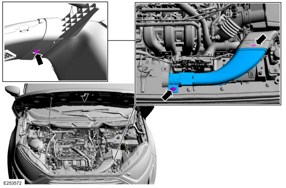 |
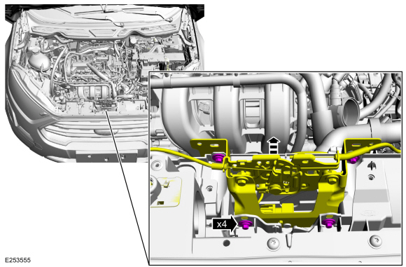
-
Remove the bolts and separate the hood latch and bracket.
Torque: 42 lb.in (4.8 Nm)
 |
-
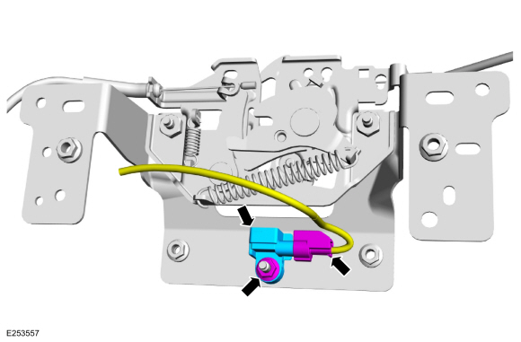
Detach the wiring harness retainer.
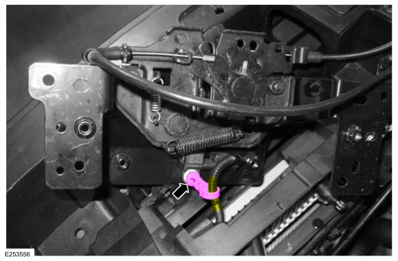 |
-
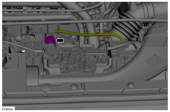
Disconnect the electrical connector, remove the nut and front impact severity sensor.
Torque: 93 lb.in (10.5 Nm)
 |
Installation
-
NOTE: The front impact severity sensor mating surfaces must be smooth and allow for a flush attachment to each other.
To install, reverse the removal procedure.
-
Repower the SRS .
Refer to: Supplemental Restraint System (SRS) Repowering (501-20B Supplemental Restraint System, General Procedures).
 Removal and Installation - Front Door Side Impact Sensor - Vehicles With: Rear Seat Side Airbag
Removal
WARNING:
The following procedure prescribes critical repair steps
required for correct restraint system operation during a crash...
 Removal and Installation - Front Impact Severity Sensor - Vehicles With: Rear Seat Side Airbag
Removal
WARNING:
The following procedure prescribes critical repair steps
required for correct restraint system operation during a crash...
Other information:
Ford Ecosport 2014-2026 Service and Repair Manual: Description and Operation - Anti-Lock Brake System (ABS) - System Operation and Component Description
System Operation System Diagram Item Description 1 HS-CAN 2 HCU 3 PCM 4 IPC 5 ABS module 6 LH front wheel speed sensor 7 RH front wheel speed sensor 8 LH rear wheel speed sensor 9 RH rear wheel speed sensor 10 Hydraulic pum..
Ford Ecosport 2014-2026 Service and Repair Manual: Diagnosis and Testing - Pinpoint Test - DTC: Q, Vehicles With: Rear Seat Side Airbag
B00D5:11, B00D5:12 and B00D5:13 Refer to Wiring Diagrams Cell 46 for schematic and connector information. Normal Operation and Fault Conditions The RCM briefly activates each LED in the PAD indicator to prove-out and verify correct functional operation of the PAD indicator to the occupants. The RCM monitors the PAD indicator power supply and "OFF" LED circuits for the follo..
Categories
- Manuals Home
- 2nd Gen Ford Ecosport Service Manual (2014 - 2026)
- Removal and Installation - Roof Rail
- Specifications
- Removal and Installation - Blower Motor
- Service Information
- Automatic Transmission - 6-Speed Automatic Transmission – 6F35
Removal and Installation - Oil Pressure Switch
Materials
Name Specification Motorcraft® Thread Sealant with PTFETA-24-B WSK-M2G350-A2
Removal
NOTE: Removal steps in this procedure may contain installation details.
With the vehicle in NEUTRAL, position it on a hoist.Refer to: Jacking and Lifting - Overview (100-02 Jacking and Lifting, Description and Operation).
If equipped, remove the bolts and the underbody shield.