Ford Ecosport: Interior Trim and Ornamentation / Removal and Installation - B-Pillar Trim Panel
Removal
NOTE: RH shown, LH similar.
NOTE: Removal steps in this procedure may contain installation details.
Upper and Lower B-Pillar Trim Panels
-
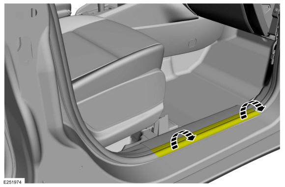
Position the front door weatherstrip aside.
 |
-
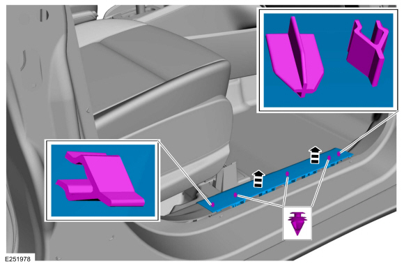
Release the clips and remove the front door scuff plate trim panel.
 |
-
Position the rear door weatherstrip aside.
 |
-
Release the clips and remove the rear door scuff plate trim panel.
 |
-
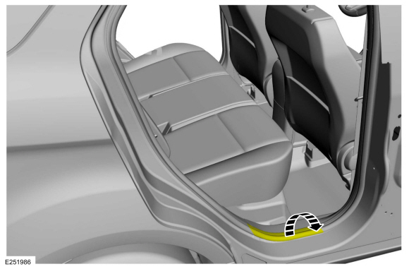
NOTE: Front seat removed for clarity.
Position the front and rear door weatherstrip aside.
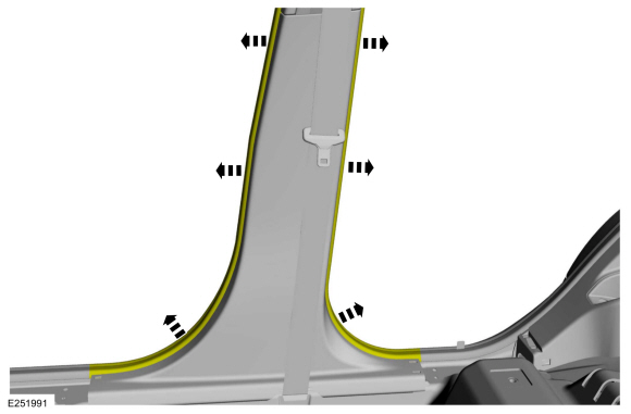 |
-
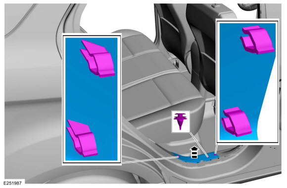
Release the clips and remove the lower B-pillar trim panel.
 |
Upper B-Pillar Trim Panel
-
Position the front and rear door weatherstrip aside.
 |
-
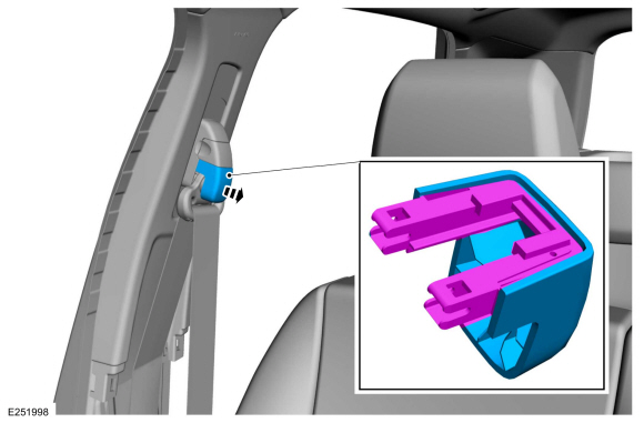
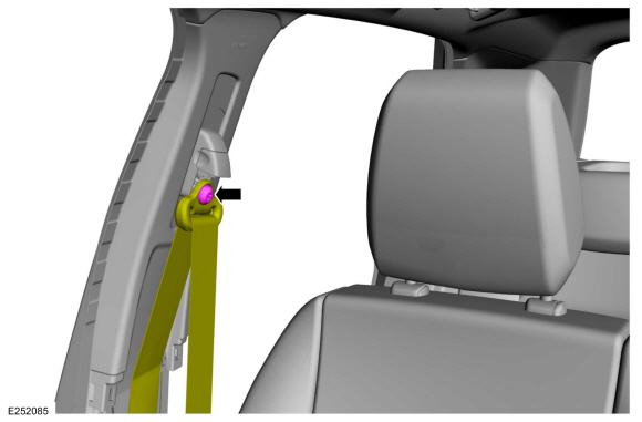
Pull straight off to release the retainers and remove the D-ring bolt cover.
 |
-
Remove the D-ring bolt and position the front seatbelt aside.
Torque: 30 lb.ft (40 Nm)
 |
-
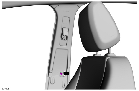
Remove the upper B-pillar trim panel bolt.
Torque: 53 lb.in (6 Nm)
 |
-
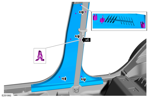
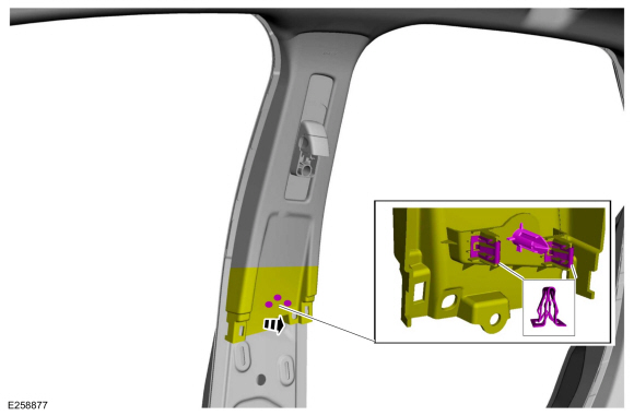
Release the upper B-pillar trim panel lower clips and locator pin.
 |
-
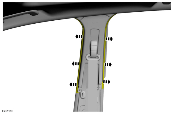
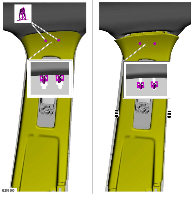
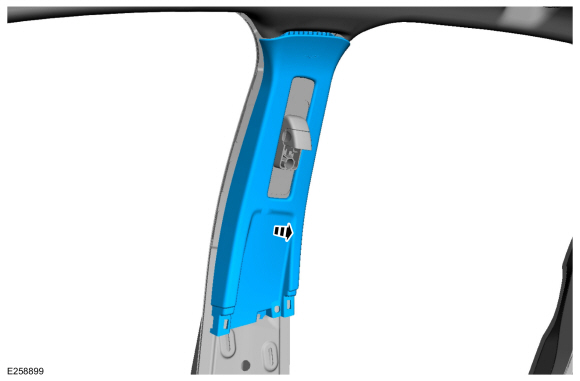
NOTICE: The upper B-pillar trim panel must be positioned downward to allow the upper clips to release correctly. Failure to follow this direction may cause damage to the upper B-pillar trim panel.
Slide the upper B-pillar trim panel down, aligning the clips to the slots in the sheet metal.
 |
-
Remove the upper B-pillar trim panel.
 |
Installation
-
NOTE: During installation, make sure the seatbelt webbing is not twisted and seatbelts and buckles are accessible to the occupants.
To install, reverse the removal procedure.
 Removal and Installation - A-Pillar Trim Panel
Removal
NOTE:
RH shown, LH similar.
Position the front door weatherstrip aside.
Disconnect the tether clip from the A-pillar trim panel...
 Removal and Installation - C-Pillar Lower Trim Panel
Removal
NOTE:
RH shown, LH similar.
Position the rear door weatherstrip aside.
Release the clips and remove the rear door scuff plate trim panel...
Other information:
Ford Ecosport 2014-2026 Service and Repair Manual: Diagnosis and Testing - Electronic Engine Controls
Diagnostic Trouble Code (DTC) Chart Diagnostics in this manual assume a certain skill level and knowledge of Ford-specific diagnostic practices. REFER to: Diagnostic Methods (100-00 General Information, Description and Operation). Module DTC Description Action PCM P0604:00 Internal Control Module Random Access Memory (RAM) Error: No Sub Type Information GO to Pinpo..
Ford Ecosport 2014-2026 Service and Repair Manual: Description and Operation - Rear Suspension - Component Location
Item Description 1 Spring 2 Shock absorber 3 Stabilizer bar link 4 Stabilizer bar 5 Differential carrier rear bush 6 Rear lower arm 7 Wheel hub 8 Rear wheel knuckle 9 Upper arm 10 Trailing arm bush ..
Categories
- Manuals Home
- 2nd Gen Ford Ecosport Service Manual (2014 - 2026)
- Removal and Installation - Front Seat
- Description and Operation - Evaporative Emissions - System Operation and Component Description
- General Procedures - Battery Charging
- Body and Paint
- Removal and Installation - Starter Motor
Description and Operation - Health and Safety Precautions
General Service Warnings
Review carefully the information below before beginning any repair. Following these warnings is a list of specific system warnings that must be reviewed before beginning work on any listed system.
 WARNING:
Wear eye and ear protection when servicing a vehicle.
Failure to follow this instruction may result in serious personal
injury.
WARNING:
Wear eye and ear protection when servicing a vehicle.
Failure to follow this instruction may result in serious personal
injury.