Ford Ecosport: Fuel Charging and Controls - 2.0L Duratec-HE (129kW/175PS) / Removal and Installation - Throttle Body
Removal
NOTICE: The turbocharger compressor vanes can be damaged by even the smallest particles. When removing any turbocharger or engine air intake system component, ensure that no debris enters the system. Failure to do so may result in damage to the turbocharger.
-
If equipped, remove the engine appearance cover.
 |
-
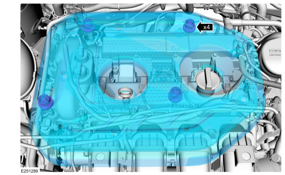
Remove the air cleaner outlet pipe.
Refer to: Air Cleaner Outlet Pipe (303-12C Intake Air Distribution and Filtering - 2.0L Duratec-HE (129kW/175PS), Removal and Installation).
-
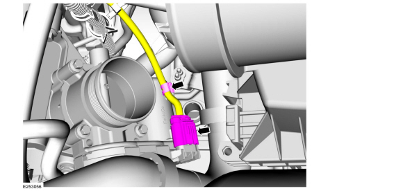
NOTE: When disconnecting the throttle body electrical connector disengage the locking tab on the throttle body electrical connector by sliding it to the rear of the throttle body electrical connector, away from the throttle body. Squeeze the throttle body electrical connector while removing.
Detach the throttle body harness retainer, then disconnect the throttle body electrical connector.
 |
-
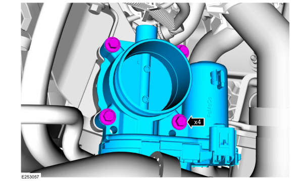
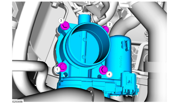
Remove the throttle body bolts, then remove the throttle body.
 |
Installation
NOTICE: Make sure that the mating faces are clean and free of foreign material.
-
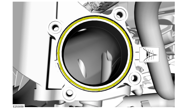
Inspect the throttle body gasket, clean and replace the throttle body gasket as needed.
 |
-
Install the throttle body, then install and tighten the throttle body bolts, in the sequence shown.
Torque: 89 lb.in (10 Nm)
 |
-
NOTE: When connecting the throttle body electrical connector engage the connector locking tab after fully installing the throttle body electrical connector. The tab will not slide forward unless the throttle body electrical connector is fully installed.
Connect the throttle body electrical connector, then attach the throttle body harness retainer.
|
-
Install the air cleaner outlet pipe.
Refer to: Air Cleaner Outlet Pipe (303-12C Intake Air Distribution and Filtering - 2.0L Duratec-HE (129kW/175PS), Removal and Installation).
-
If equipped, install the engine appearance cover.
|
 Removal and Installation - High-Pressure Fuel Pump Drive Unit
Removal
Remove the high-pressure fuel pump.
Refer to: High-Pressure Fuel Pump (303-04C Fuel Charging and Controls -
2.0L Duratec-HE (129kW/175PS), Removal and Installation)...

Other information:
Ford Ecosport 2014-2026 Service and Repair Manual: Description and Operation - Active Grille Shutter - System Operation and Component Description
System Operation System Diagram Item Description 1 ABS 2 HS-CAN 3 Grille Shutter Actuator 4 PCM 5 LIN Network Message Chart PCM Network Input Messages Broadcast Message Originating Module Message Purpose ..
Ford Ecosport 2014-2026 Service and Repair Manual: General Procedures - Transmission Fluid Drain and Refill
Materials Name Specification Motorcraft® MERCON® LV Automatic Transmission FluidXT-10-QLVC WSS-M2C938-AMERCON® LV, Draining With the vehicle in NEUTRAL, position it on a hoist. Refer to: Jacking and Lifting - Overview (100-02 Jacking and Lifting, Description and Operation). If equipped, remove the bolts and the u..
Categories
- Manuals Home
- 2nd Gen Ford Ecosport Service Manual (2014 - 2026)
- Diagnosis and Testing - Evaporative Emissions
- Removal and Installation - Catalytic Converter
- Engine
- Description and Operation - Jacking and Lifting - Overview
- Service Information
Disassembly - Engine
Special Tool(s) / General Equipment
 205-153
(T80T-4000-W)
205-153
(T80T-4000-W)
Handle
 303-103
(T74P-6375-A)
303-103
(T74P-6375-A)
Holding Tool, Flywheel
T74P-77000-A
TKIT-2009TC-F
 303-1247
VCT Spark Plug Tube Seal Remover and Installer
TKIT-2006UF-FLM
TKIT-2006UF-ROW
 303-15