Ford Ecosport: Exterior Lighting / Description and Operation - Exterior Lighting - System Operation and Component Description
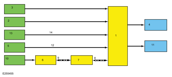
System Operation
Headlamps
System Diagram
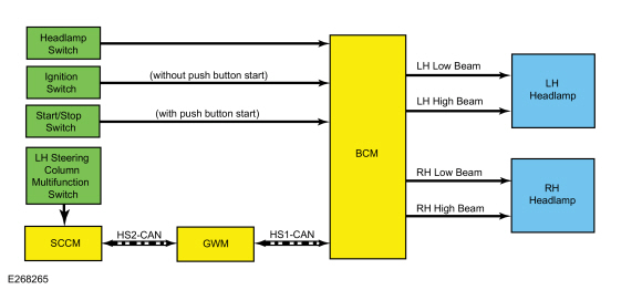
| Item | Description |
|---|---|
| 1 | (without push button start) |
| 2 | (with push button start) |
| 3 | LH low beam |
| 4 | LH high beam |
| 5 | RH low beam |
| 6 | RH high beam |
| 7 | HS-CAN2 |
| 8 | BCM |
| 9 | LH Headlamp |
| 10 | RH Headlamp |
| 11 | SCCM |
| 12 | Headlamp switch |
| 13 | LH steering column multifunction switch |
| 14 | GWM |
| 15 | Ignition switch |
| 16 | HS-CAN1 |
| 17 | Start/Stop switch |
Network Message Chart
BCM Network Input Messages
| Broadcast Message | Originating Module | Message Purpose |
|---|---|---|
| Headlamp flash to pass status | SCCM | Indicates to the BCM a request for the high beams or flash-to-pass. |
Low Beams
The BCM monitors the headlamp switch position by sending voltage signals on multiple circuits to the headlamp switch. There is one circuit for each headlamp switch position. At any given time, one of the signal circuits is switched to ground to indicate the headlamp switch position.
The BCM turns the parking lamps and headlamps on when the ignition is in RUN and the BCM detects a fault from the headlamp switch or wiring. This is normal behavior of the BCM when a fault has been detected with the inputs from the headlamp switch.
When the BCM receives a message requesting the headlamps on, it supplies voltage to the low beam bulb in each headlamp assembly.
The BCM
also provides Field Effect Transistor (FET) protection of the low beam
output circuits. When an excessive current draw is detected, the BCM disables the affected circuit driver.
Refer
to: Module Controlled Functions - System Operation and Component
Description (419-10 Multifunction Electronic Modules, Description and
Operation).
High Beams
The SCCM monitors the high beam button for a high beam request. When the LH steering column multifunction switch is pushed, the SCCM sends a message over the HS-CAN2 to the GWM , then the GWM sends the message to the BCM over the HS-CAN1 .
When the low beams are on and the BCM receives a request for high beams, the low beam bulbs remain illuminated and the high beam bulbs are also illuminated. This changes the headlamp beam pattern to illuminate a greater distance.
The BCM
also provides Field Effect Transistor (FET) protection of the high
beam output circuits. When an excessive current draw is detected, the BCM disables the affected circuit driver.
Refer
to: Module Controlled Functions - System Operation and Component
Description (419-10 Multifunction Electronic Modules, Description and
Operation).
Flash-To-Pass
The SCCM monitors the LH steering column multifunction switch for a flash-to-pass request. When the LH steering column multifunction switch is pulled briefly, the SCCM sends a message over the HS-CAN2 to the GWM then the GWM sends the message to the BCM over the HS-CAN1 .
Headlamp Exit Delay
When the ignition is OFF and the parking lamps and low beams are illuminated. They remain illuminated until:
- 3 minutes have elapsed with a door open.
- 30 seconds have elapsed after all doors are closed.
- the ignition switches to RUN.
Within the 30 second delay and all the doors closed, opening any door results in the 3 minute timer restarting.
DRL
System Diagram
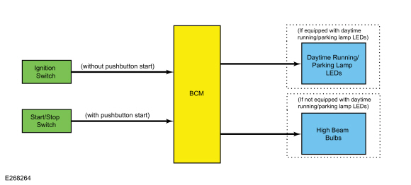
| Item | Description |
|---|---|
| 1 | BCM |
| 2 | (without pushbutton start) |
| 3 | Ignition switch |
| 4 | Start/Stop switch |
| 5 | Daytime running/parking lamp Light Emitting Diodes (LEDs) |
| 6 | (with pushbutton start) |
| 7 | High beam bulbs |
| 8 | (If equipped with daytime running/parking lamp Light Emitting Diodes (LEDs)) |
| 9 | (If not equipped with daytime running/parking lamp Light Emitting Diodes (LEDs)) |
DRL
For vehicles equipped with daytime running/parking lamp Light Emitting Diodes (LEDs) inside the headlamp assembly, when the ignition is ON, BCM provides voltage to the headlamp and the daytime running/parking Light Emitting Diodes (LEDs) in the headlamp assembly illuminate at full intensity. Then the parking lamps or headlamps are on, the daytime running/parking Light Emitting Diodes (LEDs) in the headlamp assembly illuminate at a reduced intensity
For vehicles not equipped with daytime running/parking lamp Light Emitting Diodes (LEDs) inside the headlamp assembly, the DRL system illuminates the high beam bulbs at a reduced intensity when the ignition is on and the headlamp switch is in the OFF or AUTOLAMPS position
There are two types of DRL , conventional (where it is required) and configurable.
When equipped with conventional DRL , the DRL are active in any headlamp switch position except the HEADLAMPS position.
The conventional DRL are activated when the following conditions are met:
- the ignition is ON
- the headlamps switch is in OFF, PARKLAMPS or AUTOLAMPS position and the headlamps have not been turned on by the autolamp system.
- the transmission is not in PARK
When equipped with configurable DRL , the DRL may be enabled through the IPC message center. When enabled, the DRL are active only in the AUTOLAMPS headlamp position. When autolamps request the headlamps on, the DRL are de-activated.
The configurable DRL are activated when the following conditions are met:
- the ignition is ON.
- the headlamps switch is in AUTOLAMPS position and the headlamps have not been turned on by the autolamp system.
- the transmission is not in PARK.
The BCM also provides Field Effect Transistor (FET) protection of
the DRL output circuits. When an excessive current draw is detected, the
BCM disables the affected circuit driver.
Refer to: Module
Controlled Functions - System Operation and Component Description
(419-10 Multifunction Electronic Modules, Description and Operation).
Autolamps
System Diagram
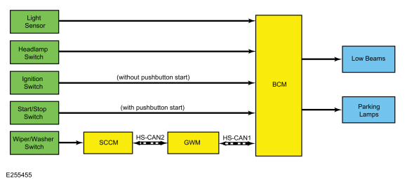
| Item | Description |
|---|---|
| 1 | BCM |
| 2 | Headlamp switch |
| 3 | Light sensor |
| 4 | Low beams |
| 5 | Start/Stop switch |
| 6 | SCCM |
| 7 | GWM |
| 8 | HS-CAN1 |
| 9 | HS-CAN2 |
| 10 | Wiper/Washer switch |
| 11 | Parking lamps |
| 12 | (with pushbutton start) |
| 13 | Ignition switch |
| 14 | (without pushbutton start) |
Network Message Chart
BCM Network Input Messages
| Broadcast Message | Originating Module | Message Purpose |
|---|---|---|
| Front wiper status | SCCM | The BCM uses the wiper status information for the operation of the wiper activated headlamps feature. |
Autolamps
The BCM monitors the light sensor with a voltage signal. The light sensor input to the BCM varies with the ambient light conditions.
The BCM monitors the headlamp switch circuits to indicate the headlamp switch position.
When the BCM receives a headlamp switch status indicating a request for the autolamps, the BCM monitors the light sensor for the ambient light condition. If the BCM determines the ambient light level is dark, the BCM illuminates the exterior parking and low beam lamps.
Headlamps On With Wipers On Function
When the headlamp switch is in the autolamps position, the exterior lamps turn on when the front wipers are in low or high. This feature does not activate the exterior lamps during a mist wipe, while the wipers are on to clear washer fluid during a wash condition or if the wipers are in automatic or intermittent modes.
The exterior lamps turn off when the ignition switches OFF or to ON mode, the headlamp switch is placed in the OFF position, or the front wipers are turned off. The exception to this is when the exterior lights are on because of darkness determined by the autolamp system.
Stoplamps
System Diagram
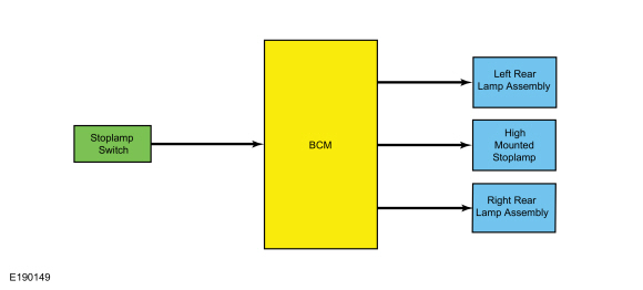
| Item | Description |
|---|---|
| 1 | BCM |
| 2 | LH rear lamp assembly |
| 3 | RH rear lamp assembly |
| 4 | Stoplamp switch |
| 5 | High mounted stoplamp |
Stoplamps
The BCM monitors the input from the stoplamp switch. When the brake pedal is applied, voltage is routed to the BCM , indicating a request for the stoplamps. The BCM then supplies voltage to the stoplamps.
The BCM uses 3 separate output circuits. The LH stoplamp output circuit, RH stoplamp output circuit and high-mounted stoplamp output circuit.
The BCM
also provides Field Effect Transistor (FET) protection of the stoplamp
output circuits. When an excessive current draw is detected, the BCM disables the affected stoplamp circuit driver.
Refer
to: Module Controlled Functions - System Operation and Component
Description (419-10 Multifunction Electronic Modules, Description and
Operation).
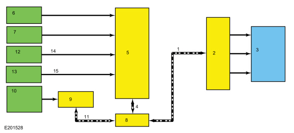
Turn Signal and Hazard Lamps
System Diagram
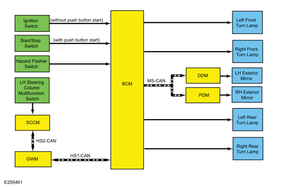
| Item | Description |
|---|---|
| 1 | (with push button start) |
| 2 | (without push button start) |
| 3 | HS-CAN2 |
| 4 | SCCM |
| 5 | GWM |
| 6 | HS-CAN1 |
| 7 | MS-CAN |
| 8 | Start/Stop switch |
| 9 | Hazard flasher switch |
| 10 | BCM |
| 11 | LH exterior mirror |
| 12 | RH exterior mirror |
| 13 | DDM |
| 14 | PDM |
| 15 | LH front turn lamp |
| 16 | Ignition switch |
| 17 | RH front turn lamp |
| 18 | LH rear turn lamp |
| 19 | RH rear turn lamp |
| 20 | LH steering column multifunction switch |
Network Message Chart
BCM Network Input Messages
| Broadcast Message | Originating Module | Message Purpose |
|---|---|---|
| Turn signal switch status | SCCM | Indicates the turn signal stalk position on the LH steering column multifunction switch (left/right lane change or turn signal on or off). The BCM activates the left/right turn signals based on this input. |
DDM and PDM Network Input Messages
| Broadcast Message | Originating Module | Message Purpose |
|---|---|---|
| Turn indication request | BCM | A command to the DDM or PDM to activate/deactivate the exterior mirror turn indicator. |
Turn Signals
The SCCM monitors the LH steering column multifunction switch position. When the LH steering column multifunction switch is in the left or right turn position, the SCCM sends a message over the HS-CAN2 to the GWM then the GWM sends the message to the BCM over the HS-CAN1 indicating a request for the LH or RH turn signal.
When the BCM receives a request for a turn signal, the BCM supplies on/off voltage to the appropriate turn lamp bulbs.
The BCM
also provides Field Effect Transistor (FET) protection of the turn
lamp output circuits. When an excessive current draw is detected, the BCM disables the affected turn lamp circuit driver.
Refer
to: Module Controlled Functions - System Operation and Component
Description (419-10 Multifunction Electronic Modules, Description and
Operation).
Hazard Lamps
The BCM sends a voltage signal to the hazard flasher lamp switch to monitor for a hazard lamp function request. When the hazard flasher lamp switch is pressed, the voltage signal is routed to ground, indicating a request to activate or deactivate the hazard lamp function.
When the BCM receives a request for the hazard lamps, the BCM supplies on/off voltage to all the turn lamps.
Parking, Rear, and License Plate Lamps
System Diagram
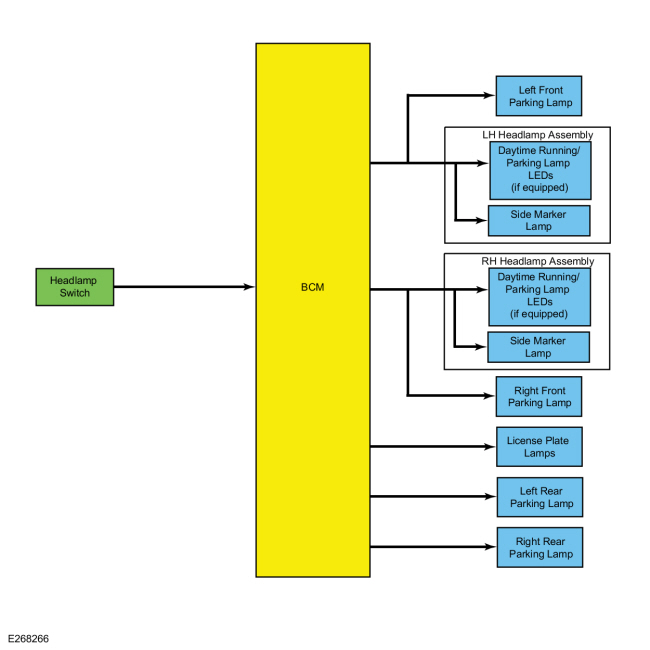
| Item | Description |
|---|---|
| 1 | BCM |
| 2 | Headlamp switch |
| 3 | LH rear parking lamp |
| 4 | RH rear parking lamp |
| 5 | License plate lamps |
| 6 | Daytime running/parking lamp Light Emitting Diodes (LEDs) (if equipped) |
| 7 | LH headlamp assembly |
| 8 | LH front parking lamp |
| 9 | RH front parking lamp |
| 10 | Side marker lamp |
| 11 | Daytime running/parking lamp Light Emitting Diodes (LEDs) (if equipped) |
| 12 | RH headlamp assembly |
| 13 | Side marker lamp |
Parking Lamps
The BCM monitors the headlamp switch position by sending voltage signals on multiple circuits to the headlamp switch. There is one circuit for each headlamp switch position. At any given time, one of the signal circuits is switched to ground to indicate the headlamp switch position.
If the BCM detects a fault from the headlamp switch or loses communication with the headlamp switch, the BCM turns the parking and headlamps on. This is normal behavior of the BCM when a fault has been detected with the inputs from the headlamp switch.
When the BCM receives a request for a parking lamps, the BCM supplies voltage to the headlamp assembly, front parking lamps, rear parking lamps and license plate lamps.
If equipped, the front the daytime running/parking Light Emitting Diodes (LEDs) in the headlamp assembly are used as parking lamps and illuminated at a reduced intensity when the parking lamps or headlamps are activated.
The BCM
also provides Field Effect Transistor (FET) protection of the parking
lamps output circuits. When an excessive current draw is detected, the BCM disables the affected parking lamps circuit driver.
Refer
to: Module Controlled Functions - System Operation and Component
Description (419-10 Multifunction Electronic Modules, Description and
Operation).
Fog Lamps
System Diagram
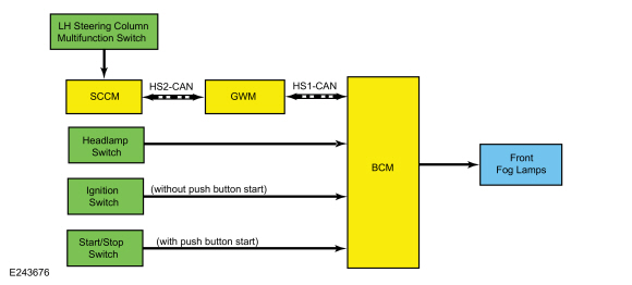

| Item | Description |
|---|---|
| 1 | BCM |
| 2 | Headlamp switch |
| 3 | Front fog lamps |
| 4 | Ignition switch |
| 5 | Start/Stop switch |
| 6 | (without push button start) |
| 7 | (with push button start) |
| 8 | SCCM |
| 9 | GWM |
| 10 | LH steering column multifunction switch |
| 11 | HS-CAN1 |
| 12 | HS-CAN2 |
Network Message Chart
BCM Network Input Messages
| Broadcast Message | Originating Module | Message Purpose |
|---|---|---|
| Headlamp flash to pass status | SCCM | Indicates to the BCM a request for the high beams or flash-to-pass. |
Fog Lamps
The BCM monitors the headlamp switch position by sending voltage signals on multiple circuits to the headlamp switch. There is one circuit for each headlamp switch position. At any given time, one of the signal circuits is switched to ground to indicate the headlamp switch position.
When the BCM receives input from the headlamp switch indicating a request for the front fog lamps, the BCM provides voltage to the front fog lamps.
The BCM
also provides an Field Effect Transistor (FET) protection of the fog
lamp output circuits. When an excessive current draw is detected, the BCM disables the fog lamp output circuit drivers.
Refer
to: Module Controlled Functions - System Operation and Component
Description (419-10 Multifunction Electronic Modules, Description and
Operation).
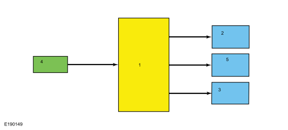
Reversing Lamps
System Diagram
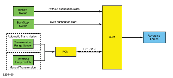
| Item | Description |
|---|---|
| 1 | BCM |
| 2 | PCM |
| 3 | HS-CAN1 |
| 4 | Reversing lamps |
| 5 | Manual transmission |
| 6 | Transmission range sensor |
| 7 | Reversing lamp switch |
| 8 | Automatic transmission |
| 9 | Start/Stop switch |
| 10 | (with pushbutton start) |
| 11 | Ignition switch |
| 12 | (without pushbutton start) |
Network Message Chart
BCM Network Input Messages
| Broadcast Message | Originating Module | Message Purpose |
|---|---|---|
| Gear position | PCM | Indicates the transmission is in reverse gear to the BCM . When the transmission is in REVERSE and the ignition in RUN, the BCM provides voltage to the reversing lamps. |
Reversing Lamps
When the transmission is in REVERSE, the PCM sends a message over the HS-CAN1 to the BCM indicating the transmission is in REVERSE. The BCM provides voltage to the reversing lamp when it receives the message that the transmission is in REVERSE and the ignition is in RUN.
If the vehicle is equipped with a manual transmission, ground is provided to the reversing lamp switch. When the gear selector is in REVERSE the switch is closed and ground is provided to the PCM .
The BCM
also provides Field Effect Transistor (FET) protection of the
reversing lamp output circuit. When an excessive current draw is
detected, the BCM disables the affected reversing lamps circuit driver.
Refer
to: Module Controlled Functions - System Operation and Component
Description (419-10 Multifunction Electronic Modules, Description and
Operation).
Trailer Lamps
System Diagram
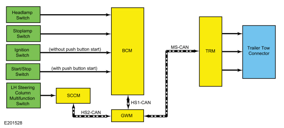
| Item | Description |
|---|---|
| 1 | MS-CAN |
| 2 | TRM |
| 3 | Trailer tow connector |
| 4 | HS-CAN1 |
| 5 | BCM |
| 6 | Headlamp switch |
| 7 | Stoplamp switch |
| 8 | GWM |
| 9 | SCCM |
| 10 | LH steering column multifunction switch |
| 11 | HS-CAN2 |
| 12 | Ignition switch |
| 13 | Start/Stop switch |
| 14 | (without push button start) |
| 15 | (with push button start) |
Network Message Chart
TRM Network Input Messages
| Broadcast Message | Originating Module | Message Purpose |
|---|---|---|
| Turn signal switch status | SCCM | A command to the TRM to activate/deactivate the turn indicator output to the trailer tow connector. |
| Stoplamp request | BCM | A command to the TRM to activate/deactivate the stop lamps output to the trailer tow connector. |
| Parklamp status | GWM | A command to the TRM to activate/deactivate the park lamps output to the trailer tow connector. |
Trailer Stop-Turn Lamps
The SCCM monitors the LH multifunction switch position. When the LH multifunction switch is in the left or right turn position, the SCCM sends a message over the HS-CAN2 to the GWM then the GWM sends the message to the BCM over the HS-CAN1 indicating a request for the LH or RH turn signal.
When the BCM receives a request for a turn signal, the BCM sends a turn indicator command message over the MS-CAN to the TRM to activate the requested turn indicator output to the trailer tow connector.
When the BCM receives input from the stoplamp switch indicating that the brake pedal is being pressed, the TRM receives a stoplamp activation message over the MS-CAN .
Trailer Parking Lamps
The BCM monitors the headlamp switch position by sending voltage signals on multiple circuits to the headlamp switch. There is one circuit for each headlamp switch position. At any given time, one of the signal circuits is switched to ground to indicate the headlamp switch position.
When the parking lamps or headlamps position is selected, the BCM sends a position light indication message over the MS-CAN to the TRM to activate the parking lamps output to the trailer tow connector.
Component Description
Headlamp Assembly
The headlamps utilize a non-serviceable module (integrated into the headlamp assembly) that is used to control the headlamp daytime running/park/turn lamps.
Exterior lamps are vented to accommodate normal changes in pressure. Condensation can be a natural by-product of this design. When moist air enters the lamp assembly through the vents, there is a possibility that condensation can occur if the temperature is cold. When normal condensation occurs, a thin mist forms on the interior of the lens. The thin mist eventually clears and exits through the vents during normal operation. The amount of time it takes to clear the lens of acceptable mist varies with ambient humidity and lamp types. Normal condensation clears from any lamp in 48 hours under dry conditions.
Do not replace a lamp assembly with acceptable levels of condensation such as:
- presence of thin mist (no streaks, drip marks or droplets are present)
- fine mist covers less than 50% of the lens
Examples of unacceptable moisture (usually caused by a lamp housing leak):
- water puddling inside the lamp
- large water droplets, drip marks or streaks present on the interior of the lens
Headlamp Switch
The BCM monitors the headlamp switch position by sending voltage signals on multiple circuits to the headlamp switch. There is one circuit for each headlamp switch position. At any given time, one of the signal circuits is switched to ground to indicate the headlamp switch position.
Light Sensor
The BCM sends a voltage signal to the light sensor. The light sensor provides resistance between the voltage signal and ground. The resistance varies depending on the amount of ambient light detected by the light sensor. The brighter the ambient light, the lower the resistance. By varying the resistance, the BCM can determine the amount of ambient light.
Stoplamp Switch
The stoplamp switch is a normally open switch and is provided voltage at all times. When the brake pedal is applied, the switch closes and routes voltage to the BCM .
 Description and Operation - Exterior Lighting - Overview
Overview
Headlamps
The
Halogen headlamp system is a quad-beam pattern system that consists of a
replaceable low beam halogen bulb and a replaceable halogen bulb for
the high beam...
 Diagnosis and Testing - Daytime Running Lamps (DRL)
DTC Chart: BCM
Diagnostics in this manual assume a certain skill level and knowledge of Ford-specific diagnostic practices. REFER to: Diagnostic Methods (100-00 General Information, Description and Operation)...
Other information:
Ford Ecosport 2014-2025 Service and Repair Manual: Removal and Installation - Rear Door Window Regulator
Special Tool(s) / General Equipment Adhesive Tape Removal NOTE: LH side shown, RH side similar. NOTE: Removal steps in this procedure may contain installation details. NOTE: For non-functional front door window regulators and motors with the window in the 40 mm open to full closed position, cut the front door window regulator cables to allow window..
Ford Ecosport 2014-2025 Service and Repair Manual: Diagnosis and Testing - Direct Clutch Assembly
Direct Clutch For direct (3,5,R) clutch operation, REFER to: Transmission Description (307-01B Automatic Transmission - 6-Speed Automatic Transmission – 6F35, Description and Operation). REFER to: Direct Clutch Assembly (307-01B Automatic Transmission - 6-Speed Automatic Transmission – 6F35, Description and Operation). Direct Clutch ..
Categories
- Manuals Home
- 2nd Gen Ford Ecosport Service Manual (2014 - 2025)
- Climate Control System - General Information
- Diagnosis and Testing - Evaporative Emissions
- Removal and Installation - Body Control Module (BCM)
- General Procedures - Transmission Fluid Level Check
- Removal and Installation - Starter Motor
Removal and Installation - Oil Pressure Switch
Materials
Name Specification Motorcraft® Thread Sealant with PTFETA-24-B WSK-M2G350-A2
Removal
NOTE: Removal steps in this procedure may contain installation details.
With the vehicle in NEUTRAL, position it on a hoist.Refer to: Jacking and Lifting - Overview (100-02 Jacking and Lifting, Description and Operation).
If equipped, remove the bolts and the underbody shield.