Ford Ecosport: Steering Wheel and Column Electrical Components / Removal and Installation - Steering Column Multifunction Switch RH
Ford Ecosport 2014-2026 Service and Repair Manual / Steering System / Steering Wheel and Column Electrical Components / Removal and Installation - Steering Column Multifunction Switch RH
Removal
NOTE: Removal steps in this procedure may contain installation details.
-
Remove the steering column shrouds.
Refer to: Steering Column Shrouds (501-05 Interior Trim and Ornamentation, Removal and Installation).
-
NOTE: Make sure that the component terminals are not bent or damaged.
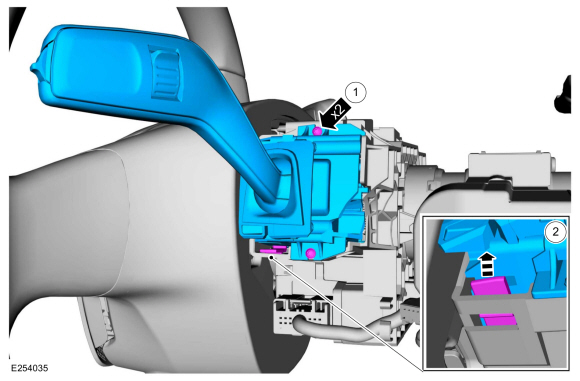
Remove the RH steering column multifunction switch.
-
Remove the retainers.
-
Depress the tab and remove the RH steering column multifunction switch.
-
Remove the retainers.
 |
Installation
-
To install, reverse the removal procedure.
 Removal and Installation - Steering Column Multifunction Switch LH
Removal
NOTE:
Removal steps in this procedure may contain installation details.
Remove the steering column shrouds.
Refer to: Steering Column Shrouds (501-05 Interior Trim and Ornamentation, Removal and Installation)...
 Removal and Installation - Ignition Switch
Removal
NOTE:
Removal steps in this procedure may contain installation details.
Remove the steering column shrouds.
Refer to: Steering Column Shrouds (501-05 Interior Trim and Ornamentation, Removal and Installation)...
Other information:
Ford Ecosport 2014-2026 Service and Repair Manual: Removal and Installation - In-Vehicle Temperature Sensor
Removal NOTE: Removal steps in this procedure may contain installation details. Remove the steering column shrouds. Refer to: Steering Column Shrouds (501-05 Interior Trim and Ornamentation, Removal and Installation). Vehicles With: Driver Knee Airbag Remove the driver knee airbag...
Ford Ecosport 2014-2026 Service and Repair Manual: Removal and Installation - Front Bumper
Special Tool(s) / General Equipment Knife Removal NOTE: Removal steps in this procedure may contain installation details. Remove the front bumper cover. Refer to: Front Bumper Cover (501-19 Bumpers, Removal and Installation)...
Categories
- Manuals Home
- 2nd Gen Ford Ecosport Service Manual (2014 - 2026)
- General Procedures - Transmission Fluid Level Check
- Removal and Installation - Rear Bumper
- Removal and Installation - Roof Rail
- Diagnosis and Testing - Evaporative Emissions
- Description and Operation - Jacking and Lifting - Overview
Removal and Installation - Rear Halfshaft Seal
Special Tool(s) / General Equipment
 205-153
(T80T-4000-W)
205-153
(T80T-4000-W)
Handle
 205-990
Installer, Axle Seal
TKIT-2012A-FL
TKIT-2012A-ROW
Copyright © 2026 www.foecosport2.com