Ford Ecosport: Steering Wheel and Column Electrical Components / Removal and Installation - Steering Column Multifunction Switch LH
Ford Ecosport 2014-2026 Service and Repair Manual / Steering System / Steering Wheel and Column Electrical Components / Removal and Installation - Steering Column Multifunction Switch LH
Removal
NOTE: Removal steps in this procedure may contain installation details.
-
Remove the steering column shrouds.
Refer to: Steering Column Shrouds (501-05 Interior Trim and Ornamentation, Removal and Installation).
-
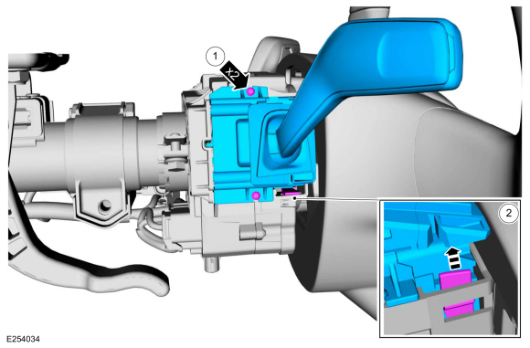
NOTE: Make sure that the component terminals are not bent or damaged.
Remove the LH steering column multifunction switch.
-
Remove the retainers.
-
Depress the tab and remove the LH steering column multifunction switch.
-
Remove the retainers.
 |
Installation
-
To install, reverse the removal procedure.
 Removal and Installation - Steering Column Lock Module (SCLM)
Special Tool(s) /
General Equipment
Flat-Bladed Screwdriver
Removal
NOTE:
Removal steps in this procedure may contain installation details...
 Removal and Installation - Steering Column Multifunction Switch RH
Removal
NOTE:
Removal steps in this procedure may contain installation details.
Remove the steering column shrouds.
Refer to: Steering Column Shrouds (501-05 Interior Trim and Ornamentation, Removal and Installation)...
Other information:
Ford Ecosport 2014-2026 Service and Repair Manual: Diagnosis and Testing - Body System
Symptom Chart(s) Diagnostics in this manual assume a certain skill level and knowledge of Ford-specific diagnostic practices. REFER to: Diagnostic Methods (100-00 General Information, Description and Operation). Dust and Water Leaks Most dust and water leaks occur due to missing or incorrectly installed body sealer or components...
Ford Ecosport 2014-2026 Service and Repair Manual: Description and Operation - Fuel Charging and Controls - Component Location
2.0L Duratec-HE Item Description 1 Throttle body 2 Fuel injector 3 High-pressure fuel pump drive unit 4 High-pressure fuel pump 5 Fuel rail Fuel Pump Driver Module Item Description 1 Fuel pump driver module ..
Categories
- Manuals Home
- 2nd Gen Ford Ecosport Service Manual (2014 - 2026)
- Diagnosis and Testing - Evaporative Emissions
- General Procedures - Transmission Fluid Level Check
- Description and Operation - Jacking and Lifting - Overview
- Removal and Installation - Rear Bumper
- Diagnosis and Testing - Body Control Module (BCM)
Removal and Installation - Wheel Knuckle Bushing
Special Tool(s) / General Equipment
Hydraulic PressRemoval
NOTE: Removal steps in this procedure may contain installation details.
Remove the wheel knuckle.Refer to: Wheel Knuckle - Vehicles With: Rear Drum Brakes (204-02B Rear Suspension - AWD, Removal and Installation).
Remove the rear toe adjustment retainers and remove the wheel knuckle mounting bracket.
Torque:
Stage 1: 177 lb.in (20 Nm)
Stage 2: 76 lb.ft (103 Nm)
Copyright © 2026 www.foecosport2.com