Ford Ecosport: Bumpers / Removal and Installation - Front Bumper Cover
Ford Ecosport 2014-2026 Service and Repair Manual / Body and Paint / Bumpers / Removal and Installation - Front Bumper Cover
Removal
NOTE: Removal steps in this procedure may contain installation details.
-
Remove the fender splash shield.
Refer to: Fender Splash Shield (501-02 Front End Body Panels, Removal and Installation).
-
On both sides.
-
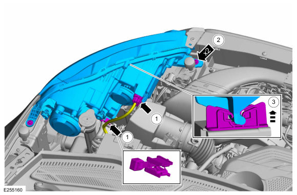
Disconnect the headlamp electrical connector and detach the wiring harness retainer.
-
Remove the screws.
Torque: 19 lb.in (2.2 Nm)
-
Remove the headlamp.
-
Disconnect the headlamp electrical connector and detach the wiring harness retainer.
 |
-
With the vehicle in NEUTRAL, position it on a hoist.
Refer to: Jacking and Lifting - Overview (100-02 Jacking and Lifting, Description and Operation).
-
NOTE: LH side only.
Detach the wiring harness retainer and disconnect the fog lamp wiring harness electrical connector.
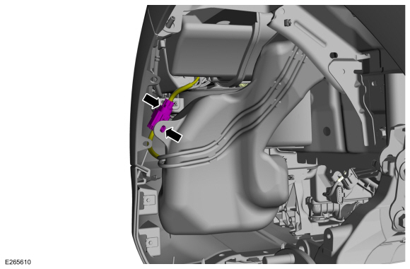 |
-
NOTE: RH side only.
Disconnect the fog lamp electrical connectors and detach the wiring harness retainer.
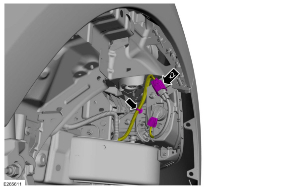 |
-
Release the tabs and position the hood lock handle aside.
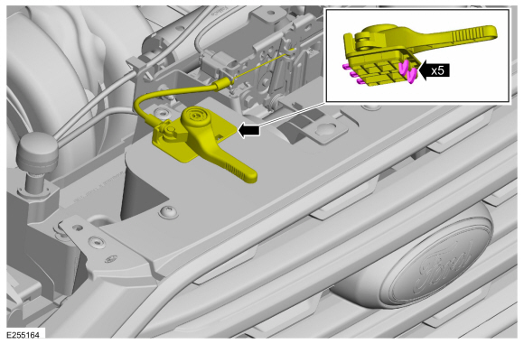 |
-
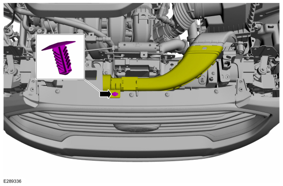
If equipped.
Remove the trim pin and position the air inlet tube aside.
 |
-
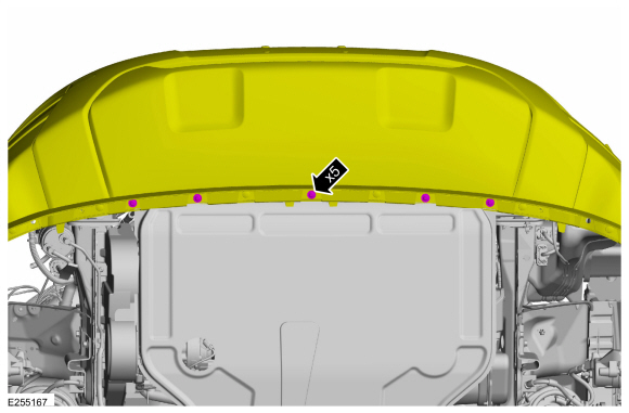
Remove the front bumper cover screws and push pins.
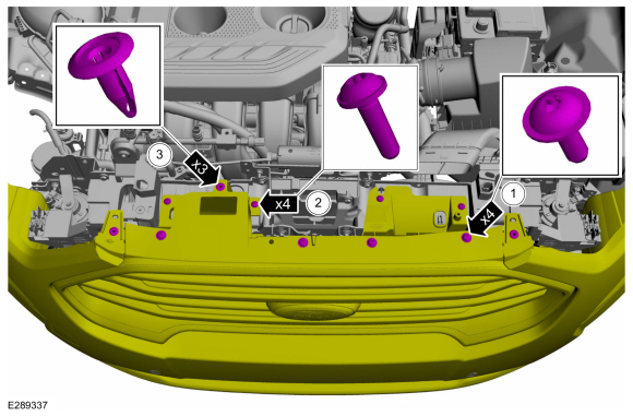 |
-
Remove the front bumper cover to air deflector bolts.
Torque: 22 lb.in (2.5 Nm)
 |
-
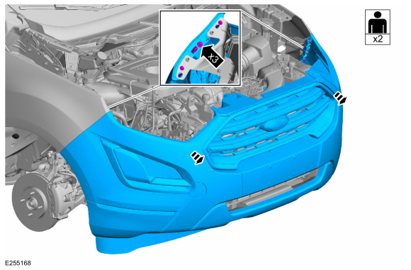
With the help of an assistant.
Remove the bolts and front bumper cover.
Torque: 42 lb.in (4.8 Nm)
 |
Installation
-
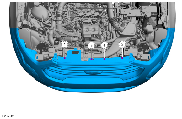
Install the front bumper cover and thighten the bolts in sequence shown.
Torque: 48 lb.in (5.4 Nm)
 |
-
To install, reverse the removal procedure.
 Removal and Installation - Front Bumper
Special Tool(s) /
General Equipment
Knife
Removal
NOTE:
Removal steps in this procedure may contain installation details.
Remove the front bumper cover...
 Removal and Installation - Rear Bumper
Removal
NOTE:
Removal steps in this procedure may contain installation details.
Remove the rear bumper cover.
Refer to: Rear Bumper Cover (501-19 Bumpers, Removal and Installation)...
Other information:
Ford Ecosport 2014-2026 Service and Repair Manual: Removal and Installation - Main Control Valve Body
Removal Remove the main control cover. Refer to: Main Control Cover (307-01B Automatic Transmission - 6-Speed Automatic Transmission – 6F35, Removal and Installation). Disconnect the TR sensor electrical connector...
Ford Ecosport 2014-2026 Service and Repair Manual: Removal and Installation - Temperature Door Actuator
Removal NOTE: Removal steps in this procedure may contain installation details. Remove the climate control housing. Refer to: Climate Control Housing (412-00 Climate Control System - General Information, Removal and Installation)...
Categories
- Manuals Home
- 2nd Gen Ford Ecosport Service Manual (2014 - 2026)
- Diagnosis and Testing - Evaporative Emissions
- Specifications
- Engine
- Removal and Installation - Roof Rail
- Automatic Transmission - 6-Speed Automatic Transmission – 6F35
Removal and Installation - Steering Column Shaft
Removal
NOTE: Removal steps in this procedure may contain installation details.
NOTICE: Do not allow the steering column to rotate while the steering column shaft is disconnected or damage to the steering column internal sensor may result.
NOTE: Use a steering wheel holding device (such as Hunter® 28-75-1 or equivalent)
Hold the steering wheel in the straight-ahead position.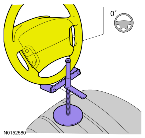
Copyright © 2026 www.foecosport2.com