Ford Ecosport: Rear Disc Brake / Removal and Installation - Brake Pads
Special Tool(s) / General Equipment
| Brake Caliper Piston Retractor |
Materials
| Name | Specification |
|---|---|
| Motorcraft® DOT 4 LV High Performance Motor Vehicle Brake Fluid PM-20 |
WSS-M6C65-A2 |
| Multi-Purpose Grease | WSS-M12A4-A2 |
Removal
NOTE: Removal steps in this procedure may contain installation details.
-
Remove the wheel and tire.
Refer to: Wheel and Tire (204-04A Wheels and Tires, Removal and Installation).
-
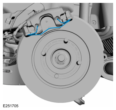
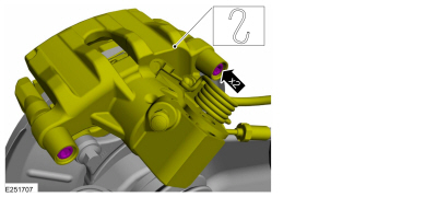
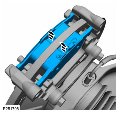
Remove the brake caliper spring.
 |
-
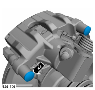
Remove the caps.
 |
-
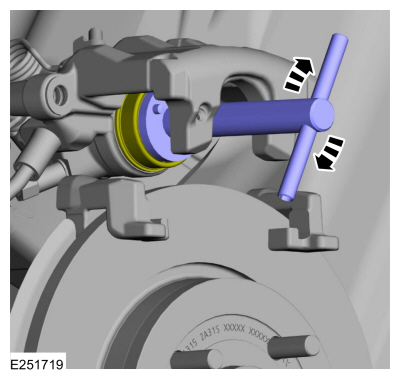
NOTICE: Do not pry in the caliper sight hole to retract the pistons as this can damage the pistons and boots.
NOTICE: Do not allow the brake caliper and anchor plate assembly to hang from the brake hose or damage to the hose can occur.
-
Remove the brake caliper guide pin bolts.
Torque: 21 lb.ft (28 Nm)
-
Position aside the brake caliper.
-
Remove the brake caliper guide pin bolts.
 |
-
Remove the brake pads.
 |
-
Retract the brake caliper piston into the brake caliper bore.
Use the General Equipment: Brake Caliper Piston Retractor
 |
Installation
-
NOTE: The inboard brake pad is equipped with a wear indicator on the trailing edge of the brake pad. The brake pad backing is marked with an arrow that indicates the rotating direction of the brake disc.
To install, reverse the removal procedure.
-
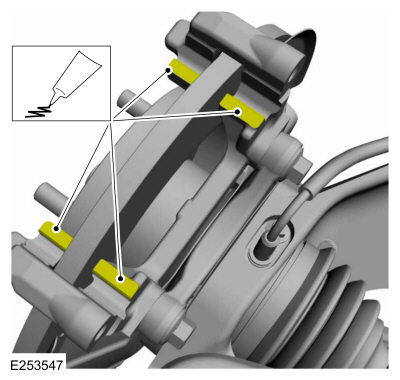
Apply the specified grease.
Material: Multi-Purpose Grease (WSS-M12A4-A2)
 |
-
Depress the brake pedal several times, check the brake
fluid level in the brake fluid reservoir and add the specified brake
fluid as necessary.
Material: Motorcraft® DOT 4 LV High Performance Motor Vehicle Brake Fluid / PM-20 (WSS-M6C65-A2)
 Removal and Installation - Brake Disc Shield
Removal
Vehicles With: FWD
NOTE:
Removal steps in this procedure may contain installation details.
Remove the wheel hub.
Refer to: Wheel Hub - Vehicles With: Rear Disc Brakes (204-02A Rear Suspension - FWD, Removal and Installation)...
 Removal and Installation - Rear Brake Flexible Hose
Removal
All vehicles
NOTE:
Removal steps in this procedure may contain installation details.
Remove the wheel and tire.
Refer to: Wheel and Tire (204-04A Wheels and Tires, Removal and Installation)...
Other information:
Ford Ecosport 2014-2026 Service and Repair Manual: Removal and Installation - Glove Compartment
Removal Open the glove compartment. Release the golve compartment stops and remove the dampener. Fully lower and remove the glove compartment...
Ford Ecosport 2014-2026 Service and Repair Manual: Removal and Installation - Rocker Panel
Special Tool(s) / General Equipment Resistance Spotwelding Equipment Hot Air Gun Air Body Saw MIG/MAG Welding Equipment Spot Weld Drill Bit Locking Pliers Removal Remove the front door...
Categories
- Manuals Home
- 2nd Gen Ford Ecosport Service Manual (2014 - 2026)
- Removal and Installation - Blower Motor
- Description and Operation - Evaporative Emissions - System Operation and Component Description
- Diagnosis and Testing - Body Control Module (BCM)
- Automatic Transmission - 6-Speed Automatic Transmission – 6F35
- Removal and Installation - Roof Rail
Removal and Installation - Steering Column Shaft
Removal
NOTE: Removal steps in this procedure may contain installation details.
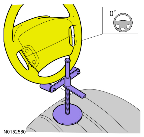
NOTICE: Do not allow the steering column to rotate while the steering column shaft is disconnected or damage to the steering column internal sensor may result.
NOTE: Use a steering wheel holding device (such as Hunter® 28-75-1 or equivalent)
Hold the steering wheel in the straight-ahead position.