Ford Ecosport: Anti-Lock Brake System (ABS) and Stability Control / Description and Operation - Anti-Lock Brake System (ABS) and Stability Control - System Operation and Component Description
System Operation
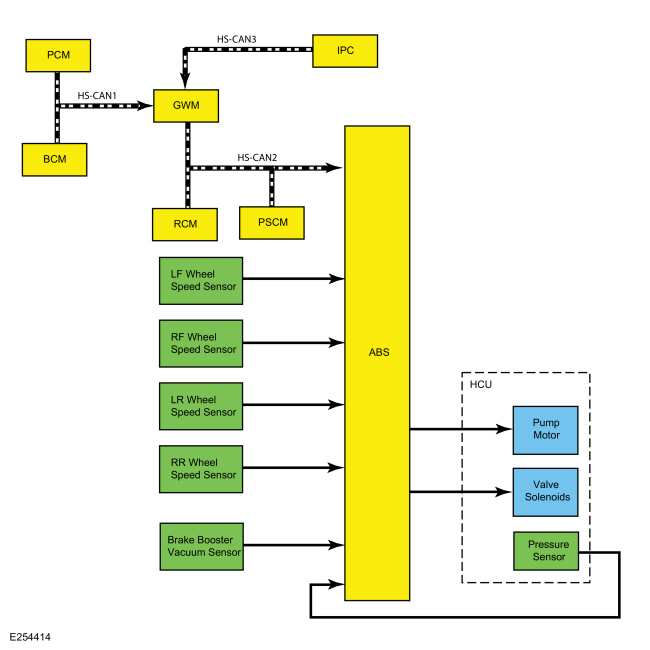
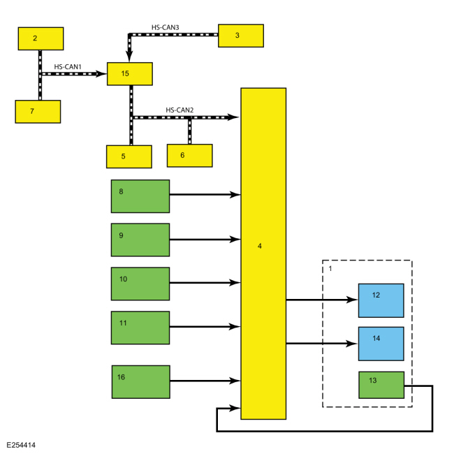
System Diagram
| Item | Description |
|---|---|
| 1 | HCU |
| 2 | PCM |
| 3 | IPC |
| 4 | ABS module |
| 5 | RCM |
| 6 | PSCM |
| 7 | BCM |
| 8 | LH Front wheel speed sensor |
| 9 | RH Front wheel speed sensor |
| 10 | LH Rear wheel speed sensor |
| 11 | LH Rear wheel speed sensor |
| 12 | Hydraulic pump motor |
| 13 | Hydraulic pressure sensor |
| 14 | Hydraulic valve solenoids |
| 15 | GWM |
| 16 | Brake booster vacuum sensor |
Network Message Chart
Module Network Input Messages - ABS Module
| Broadcast Message | Originating Module | Message Purpose |
|---|---|---|
| Accelerator pedal position | PCM | This message is first sent to the GWM and then to the ABS module. The ABS module uses accelerator pedal position information for correct operation of the traction control, ESC , RSC and hill start assist features. |
| Ambient Air Temperature | PCM | This message is first sent to the GWM and then to the ABS module. This message informs the ABS module of the current ambient air temperature. The ABS module uses this information for calculations in determining the operational status of the various stability control systems and features. |
| AWD lock status | PCM | This message is first sent to the GWM and then to the ABS module. This message informs the ABS module of the current AWD lock status; OK, opened by command, inactive, fault, warning, disabled, fully locked by command, torque limited by command, under external torque control or undefined. The ABS module uses this information for calculations in the operation of the various stability control systems and features. |
| AWD service required | PCM | This message is first sent to the GWM and then to the ABS module. This message informs the ABS module of the current AWD service required indicator; on or off. The ABS module uses this information for calculations in the operation of the various stability control systems and features. |
| Brake on-off switch | PCM | This message is first sent to the GWM and then to the ABS module. This message informs the ABS module the driver has pressed the brake pedal. This message is also used by the ABS module to check the brake pressure sensor located inside the HCU . |
| Clutch pedal position | PCM | This message is first sent to the GWM and then to the ABS module. This message informs the ABS module the driver has pressed the clutch pedal. |
| Cruise control mode | PCM | This message is first sent to the GWM and then to the ABS module. This message informs the ABS module of the current cruise control system mode; not active, keeping speed, accelerating, decelerating, resuming high, resuming low, tap up waiting or tap down waiting. |
| Cruise control override | PCM | This message is first sent to the GWM and then to the ABS module. This message informs the ABS module the PCM has overridden the cruise control request. When the ABS module receives this message, any other cruise control messages are ignored until the "not overridden" message is received. |
| Cruise control status | PCM | This message is first sent to the GWM and then to the ABS module. This message informs the ABS module the current cruise control system status; off, denied, standby denied, standby, active que assist or active. |
| Door ajar status | BCM | This message is first sent to the GWM and then to the ABS module. This message informs the ABS module of the current door ajar statuses; driver front and rear, passenger front and rear. The ABS module resets the parameters used for the ESC and RSC when a door is opened and closed. |
| Engine coolant temperature | PCM | This message is first sent to the GWM and then to the ABS module. This message informs the ABS module of the current engine coolant temperature. This information is used for fault monitoring. |
| Engine RPM data | PCM | This message is first sent to the GWM and then to the ABS module. This message informs the ABS module of the current engine speed in RPM . |
| Engine status | PCM | This message is first sent to the GWM and then to the ABS module. This message informs the ABS module of the current status of the engine; off, ready, cranking, running, stalled, after-run, or shutdown. |
| Gear lever position | PCM | This message is first sent to the PCM and then to the ABS module. This message informs the ABS module of the current driver selected gear. The hill start assist feature works in forward and reverse gears. ESC and RSC do not operate when the transmission is in REVERSE. |
| Hood ajar status | BCM | This message is first sent to the GWM and then to the ABS module. This message informs the ABS module of the current hood ajar status. The ABS module resets the parameters used for the ESC and RSC when the hood is opened and closed. |
| Ignition key type | BCM | This message is first sent to the GWM and then to the ABS module. This message informs the ABS module of the current ignition key type; MyKey or Standard Key. The ABS module may have operating mode restrictions depending on the type of ignition key used. |
| Ignition status | BCM | This message is first sent to the GWM and then to the ABS module. This message informs the ABS module of the current ignition status; off, accessory, run, start, unknown or invalid. |
| Key in ignition status | BCM | This message is first sent to the GWM and then to the ABS module. This message informs the ABS module of the current key in ignition status; in or out. |
| Liftgate ajar status | BCM | This message is first sent to the GWM and then to the ABS module. This message informs the ABS module of the current liftgate ajar status. The ABS module resets the parameters used for the ESC and RSC when the liftgate is opened and closed. |
| Odometer master value | IPC | This message is sent to the GWM and then to the ABS module. This message informs the ABS module of the current odometer mileage. |
| Parking brake status | BCM | This message is first sent to the GWM and then to the ABS module. This message informs the ABS module of the current parking brake status: applied or released. |
| PATS start request target command | PCM | This message is first sent to the GWM and then to the ABS module. This message provides the ABS module with the challenge and password for anti-theft vehicle starting. During vehicle starting, the PCM and the ABS module exchange information to make sure the vehicle is being started correctly. |
| PATS start request target status | PCM | This message is first sent to the GWM and then to the ABS module. This message informs the ABS module of the current anti-theft start request status; disabled, enabled motive start, enabled non-motive start, disabled reset. |
| RCM serial number | RCM | The ABS module stores the RCM serial number and verifies the serial number when the vehicle is started or the ignition is set to run or accessory. Over time, the ABS module learns the offset of the sensors inside the RCM . When a new serial number is found and the IVD Initialization procedure is carried out using a scan tool, the ABS module resets the offset number learned for ESC and RSC . |
| Steering pinion angle | PSCM | The ABS module uses steering angle information for ESC and RSC operation. This message provides the ABS with the current steering wheel angle and direction of rotation. |
| Stoplamp status | BCM | This message is first sent to the GWM and then to the ABS module. This message informs the ABS module of the current stoplamp status. This information is used for fault monitoring. |
| Vehicle configuration data | BCM | This message is first sent to the GWM and then to the ABS module. This message provides the ABS module with the current optional and configured items such as, tire size, axle ratio, manual or automatic transaxle, keyless entry, and VIN . |
| Vehicle stability control data | RCM | This message provides the ABS module with the following stability control information; longitudinal acceleration, lateral acceleration, yaw rate and roll rate. The ABS module uses this information to help maintain vehicle stability during maneuvers. |
Anti-Lock Brake System (ABS)
The ABS module continuously monitors brake pedal input, lateral vehicle motion and the rotational speed of each wheel. The ABS module receives the brake pedal input from the PCM over the HS-CAN1 through the GWM , while the RCM sends lateral acceleration sensor information to the ABS module over the HS-CAN2 . Wheel speed information is retrieved by the ABS module using 4 wheel speed sensors. When the ABS module detects an impending wheel lock during a braking event, the ABS module modulates brake pressure to the appropriate wheel ends by opening and closing the appropriate solenoid valves inside the HCU while the hydraulic pump motor is activated. Once the affected wheel(s) return to the desired speed, the ABS module returns the solenoid valves in the HCU to their normal position.
The ABS module has 2 self-test options, one uses the scan tool and the other is carried out when the ABS module is initialized (ignition ON). During either self-test the ABS module carries out a preliminary electrical check of the system sensors and activates the hydraulic pump motor for approximately one-half second. During this time, a buzzing or humming noise may be heard and a vibration may be felt in the brake pedal and is a normal condition. During the module initialized self-test, the pump motor check is carried out at approximately 20 km/h (12 mph). Any malfunction detected in the system causes the module to set a DTC , disables the ABS and send a message over the HS-CAN3 through the GWM to the IPC to illuminate the ABS warning indicator.
Electronic Brake Force Distribution (EBD)
The ABS module incorporates a strategy called EBD . The EBD strategy uses the HCU as an electronic proportioning valve. On initial application of the brake pedal, full pressure is applied to the rear brakes. The ABS module uses wheel speed sensor input to calculate an estimated rate of deceleration. Once vehicle deceleration exceeds a certain threshold, the ABS module closes the appropriate solenoid valves in the HCU to hold the rear brake pressure constant while allowing the front brake pressure to build. This creates a balanced braking condition between the front and rear wheels and minimizes the chance of rear wheel lockup during hard braking. As the vehicle decelerates, the valves open to increase the rear brake pressure in proportion to the front brake pressure.
If 2 or more wheel speed sensor Diagnostic Trouble Codes (DTCs) set in the ABS module or a HCU DTC sets in the ABS module, EBD is disabled. When EBD is disabled, the ABS warning indicator, the red brake warning indicator and the stability-traction control indicator (sliding car icon) illuminate.
Emergency Brake Assist (EBA)
The EBA feature helps drivers in emergency braking situations by applying the maximum possible braking force during a severe braking event.
If the brake pedal is pressed very suddenly, the ABS module increases the hydraulic pressure to all of the brakes until the threshold for ABS intervention is reached. This generates the maximum braking power for the available traction. The ABS module monitors inputs from the brake pedal switch and from the pressure sensor within the HCU to check for sudden actuation of the brakes. With the brake pedal pressed, the ABS module triggers emergency braking if the rate of increase of hydraulic pressure exceeds the predetermined limit.
If the brake pedal is pressed so hard the ABS becomes active on the front wheels, the ABS module increases the pressure to the rear wheel brakes up to the ABS intervention threshold.
EBA operation continues until the driver releases the brake pedal sufficiently for the hydraulic pressure in the HCU to drop below a specific threshold value. This threshold is saved in the ABS module.
Emergency Brake Light
The hazard flasher system is activated as an additional emergency brake light in the case of emergency braking. Based on a defined delay value, the ABS module sends a signal to the IPC over the HS-CAN3 through the GWM . The IPC activates the hazard flasher system, which flashes 7 times.
Prerequisites for activation of the emergency brake light are:
- The speed is higher than 50 km/h (31 mph).
- The brake pedal is being actuated.
- The deceleration is greater than 9 meters per second squared.
To prevent activation on snow or ice, for example, the following prerequisites must be met:
- The speed is higher than 50 km/h (31 mph).
- The brake pedal is being actuated.
- ABS activation is taking place.
- The deceleration is greater than 6 meters per second squared.
Vacuum On Demand System
Vehicles equipped with a 2.0L engine supply vacuum to the brake booster through the use of a valve solenoid and an aspirator in the brake booster vacuum tube. When the ABS module detects a low vacuum condition in the brake booster, a message is sent to the PCM requesting additional vacuum. The PCM responds by opening the valve solenoid which allows the engine to draw air from the brake booster, increasing vacuum in the booster. Once the vacuum in the booster has reached the required level, the ABS module stops sending the message and the PCM closes the valve solenoid.
Traction Control
The ABS module continuously monitors and compares the rotational speed of the drive wheels to the rotational speed of the non-driven wheels. When the drive wheels begin to spin faster than the non-driven wheels, the ABS module modulates brake pressure to the appropriate wheel ends by opening and closing the appropriate solenoid valves inside the HCU while the hydraulic pump motor is activated. At the same time, the ABS module calculates how much engine torque reduction is required to eliminate the wheel slip and sends this torque reduction message to the PCM over the HS-CAN1 through the GWM . The ABS module also sends a traction event message to the IPC over the HS-CAN3 through the GWM . When the PCM receives the torque reduction message, it adjusts engine timing and decreases fuel injector pulses to reduce the engine torque to the requested level. When the IPC receives the traction event message, it flashes the stability-traction control indicator (sliding car icon). Once the driven wheel speed returns to the desired speed, the ABS module returns the solenoid valves in the HCU to their normal position, deactivates the hydraulic pump motor and stops sending the traction event and torque reduction messages. The PCM returns engine timing and fuel injectors to normal operation and the IPC extinguishes the sliding car icon. After the vehicle speed exceeds 100 km/h (62.1 mph), traction control is accomplished only through the PCM torque control.
The driver can disable the traction control feature by using the stability-traction control switch. This is independent of the ABS , ESC and RSC , which cannot be disabled by the driver. When the driver disables the traction control feature, the ABS module takes no further action in regards to traction control until the driver activates traction control or until the ignition is cycled from OFF to ON. The ABS module also sends a message to the IPC over the HS-CAN3 through the GWM . When the IPC receives this message, the stability-traction control OFF indicator (sliding car OFF icon) is illuminated.
The traction control feature is disabled if there is a wheel speed sensor or valve solenoid DTC present in the ABS module. The traction control feature is also disabled if there is a communication error between the ABS module and the PCM . Anytime traction control is disabled, the ABS module sends a message to the IPC over the HS-CAN to illuminate the sliding car OFF icon.
Electronic Stability Control (ESC)
The ABS module continuously monitors the vehicle motion relative to the intended course. This is done by using sensors to compare the steering wheel input and the yaw rate sensor input with the actual vehicle motion. The PSCM sends steering wheel angle and rate of change information, while the RCM sends yaw rate and longitudinal acceleration information to the ABS module. All 3 modules communicate over the HS-CAN2 . If the ABS module determines from the inputs the vehicle is unable to travel in the intended direction, it modulates the brake pressure to the appropriate wheel ends by opening and closing the appropriate solenoid valves inside the HCU while the hydraulic pump motor is activated. At the same time the ABS module calculates how much engine torque reduction is required to reduce vehicle speed to help stabilize the vehicle and sends this torque reduction message to the PCM over the HS-CAN1 through the GWM . The ABS module also sends a stability event message to the IPC over the HS-CAN3 through the GWM . When the PCM receives the torque reduction message, it adjusts engine timing and decreases fuel injector pulses to reduce the engine torque to the requested level. When the IPC receives this message, it flashes the stability-traction control indicator (sliding car icon). Once the vehicle instability has been corrected, the ABS module returns the solenoid valves in the HCU to their normal position, deactivates the hydraulic pump motor and stops sending the traction event and torque reduction messages. The PCM returns engine timing and fuel injectors to normal operation and the IPC extinguishes the sliding car icon.
The ESC feature does not operate with the transmission in REVERSE. The ESC feature is disabled if there is a wheel speed sensor, stability sensor or steering angle sensor DTC present in the ABS module. Also, if there is a communication error between the ABS module and the PSCM or the ABS module and the RCM , the ESC feature is disabled. When the ESC feature is disabled, the ABS module sends a message to the IPC over the HS-CAN3 through the GWM to illuminate the stability-traction control OFF indicator (sliding car OFF icon).
Roll Stability Control (RSC)
The ABS module continuously monitors the vehicle motion relative to the intended course. This is done by using sensors to compare the steering wheel input and the stability control sensor inputs with the actual vehicle motion. The PSCM sends steering wheel angle and rate of change information, while the RCM sends yaw rate, longitudinal acceleration and roll rate information to the ABS module. All 3 modules communicate over the HS-CAN2 . If the ABS module determines from the inputs the vehicle is unable to travel in the intended direction, it modulates the brake pressure to the appropriate wheel ends by opening and closing the appropriate solenoid valves inside the HCU while the hydraulic pump motor is activated. At the same time the ABS module calculates how much engine torque reduction is required to reduce vehicle speed to help stabilize the vehicle and sends this torque reduction message to the PCM over the HS-CAN1 through the GWM . The ABS module also sends a stability event message to the IPC over the HS-CAN3 through the GWM . When the PCM receives the torque reduction message, it adjusts engine timing and decreases fuel injector pulses to reduce the engine torque to the requested level. When the IPC receives this message, it flashes the stability-traction control indicator (sliding car icon). Once the vehicle instability has been corrected, the ABS module returns the solenoid valves in the HCU to their normal position, deactivates the hydraulic pump motor and stops sending the traction event and torque reduction messages. The PCM returns engine timing and fuel injectors to normal operation and the IPC extinguishes the sliding car icon.
The RSC feature does not operate with the transmission in REVERSE. The RSC feature is disabled if there is a wheel speed sensor, stability sensor or steering angle sensor DTC present in the ABS module. Also, if there is a communication error between the ABS module and the PSCM or the ABS module and the RCM , the RSC feature is disabled. When the RSC feature is disabled, the ABS module sends a message to the IPC over the HS-CAN3 through the GWM to illuminate the stability-traction control OFF indicator (sliding car OFF icon).
Hill Start Assist
When the vehicle is stopped on an incline greater than 1.5 degrees (approximately a 3% grade), the ABS module holds the brake pressure for up to 3 seconds while the driver transitions from the brake pedal to the accelerator pedal. This is accomplished by monitoring several HS-CAN messages and several sensors to determine if the vehicle is stopped and not parked, and if the vehicle is on an appropriate incline. The brake pedal position message from the PCM , along with wheel speed sensor inputs allow the ABS module to determine the vehicle has come to a complete stop. The transmission selector lever message sent by the PCM informs the ABS module the vehicle is not parked. The stability sensor messages sent by the RCM enable the ABS module to determine if the vehicle is on an incline greater than 1.5 degrees (approximately a 3% grade). Once the above conditions have been met, the hill start assist feature automatically engages. As the driver releases the brake pedal, the ABS module commands the HCU to close the isolation valves which maintains the current brake system pressure, preventing the vehicle from rolling down the incline. Once the driver presses the accelerator pedal and the engine RPM increases, the ABS module gradually releases the brake pressure to make sure the vehicle is neither rolling back nor driving off until there is sufficient driving torque to accelerate the vehicle forward (or backward if reversing up the incline).
MyKey Interaction (If Equipped)
Through the MyKey feature, if equipped, traction control can be configured to be always on or to allow the driver to select traction control on or off. When the MyKey traction control feature is configured to be always on and a MyKey restricted key is in use, the ABS module ignores any requests made by the driver to disable traction control. Refer to the Owner's Literature for additional information on the MyKey feature and settings.
Stability-Traction Control Indicator (Sliding Car Icon)
One or both of the stability-traction control indicators may illuminate as a result of momentary sensor disturbances due to environmental or driving conditions (including severe vehicle maneuvers or extreme off road usage). Once Illuminated, the indicator remains illuminated until the environmental or driving condition is no longer present and the ignition is cycled from ON to OFF and then back to ON again. If there are no other customer concerns, symptoms, indicators or Diagnostic Trouble Codes (DTCs), the stability-traction control indicator may have been illuminated due to these environmental or driving conditions.
Refer to: Instrument Panel Cluster (IPC) - System Operation and
Component Description (413-01 Instrumentation, Message Center and
Warning Chimes, Description and Operation).
Stability-Traction Control Disabled Indicator (Sliding Car OFF Icon)
Refer to: Instrument Panel Cluster (IPC) - System Operation and
Component Description (413-01 Instrumentation, Message Center and
Warning Chimes, Description and Operation).
Component Description
Anti-Lock Brake System (ABS) Module
The ABS module is attached directly to the HCU and is the ECU for all of the ABS and stability control systems. The ABS module monitors all sensor inputs and all HS-CAN messages relating to ABS and stability control, then directly controls the solenoid valves and the hydraulic pump motor in the HCU .
The ABS module and HCU are connected together but are serviced
separately. When a new ABS is installed, the module must be programmed
with the vehicle information.
Refer to: Communications Network -
System Operation and Component Description (418-00 Module Communications
Network, Description and Operation).
When an ABS or stability control system fault has been corrected or a new component has been installed, the ABS module must be calibrated. The calibration procedure is required for the stability control sensors to learn the zero-position of the vehicle which means the vehicle must be on a level surface and not moving. The calibration procedure (IVD Initialization Routine) is carried out using a scan tool.
Hydraulic Control Unit (HCU)
The HCU contains the solenoid valves, the hydraulic pump motor and the pressure sensor used by the ABS module for the ABS and stability control system. The ABS module and HCU are connected together but are serviced separately.
Stability Control Sensors
The stability control sensors for the traction control, ESC and RSC features consist of the yaw rate sensor, lateral accelerometer and longitudinal accelerometer. The sensors are housed in the RCM which transmits sensor information to the ABS module over the HS-CAN2 . If any of the sensors are defective, a new RCM must be installed.
- The yaw rate sensor measures the yaw angle which is the difference between the direction the vehicle is pointing when cornering and the direction the vehicle is actually moving.
- The longitudinal accelerometer measures the acceleration and deceleration of the vehicle as it moves forward and backward.
- The lateral accelerometer measures the sideways, pushing force created when a vehicle corners.
- The roll rate sensor measures the rate of rotation of the vehicle along the centerline of the vehicle from front to back.
Lateral acceleration has 2 forms. The first is the centrifugal acceleration generated when the vehicle travels around in a circle. The second is the acceleration due to gravity. On level ground there is no lateral acceleration due to gravity. However, if the vehicle is parked sideways on a bank or incline, the sensor measures some lateral acceleration due to gravity, even though the vehicle is not moving.
Wheel Speed Sensor
The wheel speed sensors are active (magneto resistive) sensors operating on the Hall-effect principle to generate a square wave signal proportional to the rotational speed of the wheel. Because these are active sensors, receiving voltage from the ABS module and then sending a varying voltage back to the module, they are able to detect much lower rotational speeds than passive (magnetic inductive) sensors. Each wheel speed sensor is connected to the ABS module by 2 circuits which are used for both sensor power and sensor signal return.
Wheel Speed Sensor Encoders
The wheel speed sensor encoders are several magnets arranged in a circle around one side of the wheel bearing in alternating poles. As the wheel bearing rotates, the wheel speed sensor is exposed to alternating north-south magnetic fields. The encoder is part of the wheel bearing and is serviced with the bearing.
 Description and Operation - Anti-Lock Brake System (ABS) and Stability Control - Overview
Overview
The ABS
and stability control systems are comprised of the following
subsystems which assist the driver in maintaining control of the
vehicle:
ABS
EBA
EBD
ESC
Hill start assist
Traction control
The ABS helps maintain steering control by preventing the wheels
from locking up during hard braking...
 Removal and Installation - Anti-Lock Brake System (ABS) Module
Removal
NOTE:
Removal steps in this procedure may contain installation details.
NOTE:
The PMI process must begin with the current ABS module installed...
Other information:
Ford Ecosport 2014-2026 Service and Repair Manual: General Procedures - Reset the Outside Air Temperature Sensor Learned Values
Configuration NOTE: The ambient air temperature sensor is a critical component for correct Air Conditioning (A/C) and Heating, Ventilation, and Air Conditioning (HVAC) system operation. Make sure after the reset is carried out the temperature is displaying correctly in the vehicle...
Ford Ecosport 2014-2026 Service and Repair Manual: Removal and Installation - Rear Lamp Assembly
Removal NOTE: Removal steps in this procedure may contain installation details. Liftgate reflector NOTE: LH rear lamp assembly shown. RH rear lamp assembly similar. Refer to: Liftgate Trim Panel (501-05 Interior Trim and Ornamentation, Removal and Installation)...
Categories
- Manuals Home
- 2nd Gen Ford Ecosport Service Manual (2014 - 2026)
- Body and Paint
- Removal and Installation - Roof Rail
- Specifications
- Removal and Installation - Catalytic Converter
- General Procedures - Battery Charging
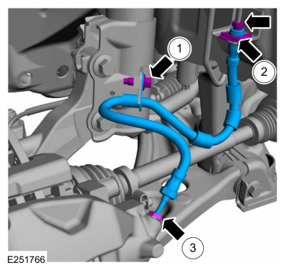
Removal and Installation - Front Brake Flexible Hose
Removal
Remove the wheel and tire.Refer to: Wheel and Tire (204-04A Wheels and Tires, Removal and Installation).
Remove the brake flexible hose bracket bolt.
Disconnect the brake tube fitting and remove the brake hose clip.
Loosen the brake hose fitting and remove the brake flexible hose.