Ford Ecosport: Power Brake Actuation / Removal and Installation - Brake Booster - LHD
Ford Ecosport 2014-2026 Service and Repair Manual / Brake System / Power Brake Actuation / Removal and Installation - Brake Booster - LHD
Removal
NOTE: Removal steps in this procedure may contain installation details.
-
Remove the battery tray.
Refer to: Battery Tray (414-01 Battery, Mounting and Cables, Removal and Installation).
-
Remove the brake master cylinder.
Refer to: Brake Master Cylinder (206-06 Hydraulic Brake Actuation, Removal and Installation).
-
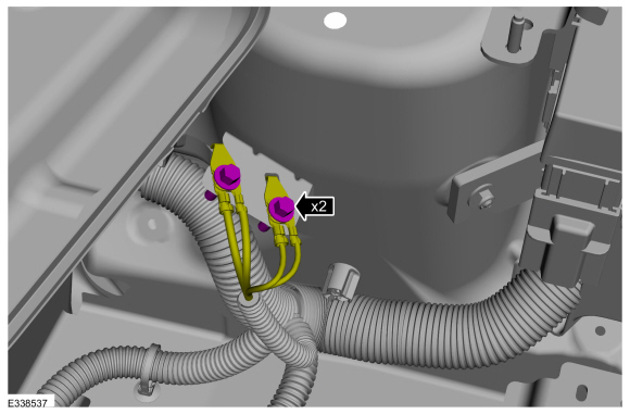
Remove the ground strap bolts.
Torque: 106 lb.in (12 Nm)
 |
-
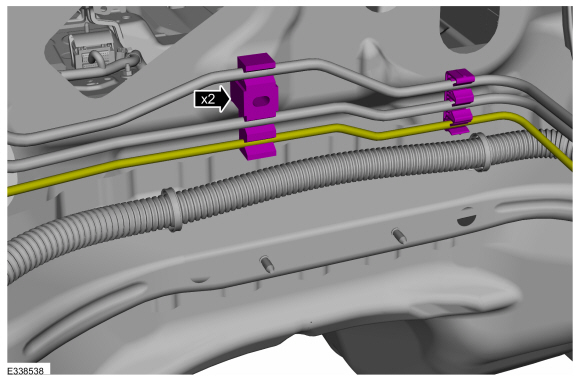
Position the brake line clip off of the bulkhead stud and release the lower brake line from the clips.
 |
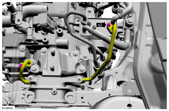
1.0L EcoBoost (92kW/125PS) (B7)
-
Remove the bolts and position aside the transmission cooler tube.
Torque: 97 lb.in (11 Nm)
 |
All vehicles
NOTICE: Do not service the brake pedal or brake booster without first removing the stoplamp switch. This switch must be removed with the brake pedal in the at-rest position. The switch plunger must be compressed for the switch to rotate in the bracket. Attempting to remove the switch when the plunger is extended (during pedal apply) will result in damage to the switch.
-
Remove the stoplamp switch.
Refer to: Stoplamp Switch (417-01 Exterior Lighting, Removal and Installation).
-
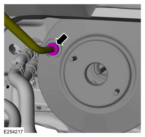
Detach the check valve from the brake booster.
 |
-
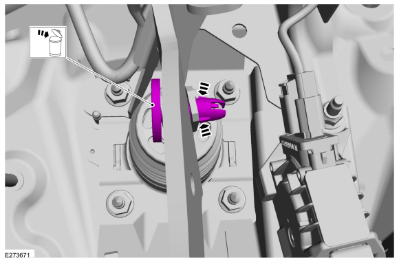
Press the tabs and remove the clevis pin. Discard the pin.
 |
-
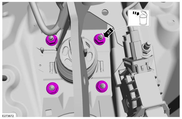
Remove and discard the brake booster nuts.
 |
-
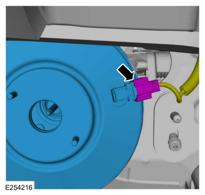
Disconnect the vacuum sensor electrical connector and remove the brake booster.
 |
Installation
NOTICE: Make sure that the brake booster pushrod is correctly located.
-
To install, reverse the removal procedure.
-
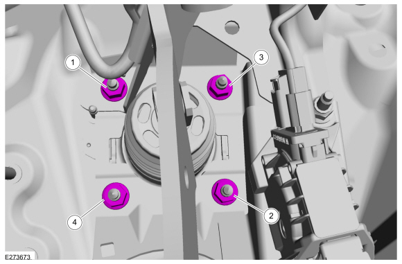
Install the brake booster and tighten the nuts in sequence.
Torque: 18 lb.ft (25 Nm)
 |


Other information:
Ford Ecosport 2014-2026 Service and Repair Manual: Removal and Installation - Roof Rear Frame
Special Tool(s) / General Equipment Resistance Spotwelding Equipment Spot Weld Drill Bit Locking Pliers Materials Name Specification Seam SealerTA-2-B, 3M™ 08308, LORD Fusor® 803DTM - Removal NOTE: Factory welds may be substituted with resistance or metal inert gas (MIG) plug welds. Resistance welds may not be placed di..
Ford Ecosport 2014-2026 Service and Repair Manual: Removal and Installation - A-Pillar Outer Panel
Special Tool(s) / General Equipment Resistance Spotwelding Equipment Spherical Cutter Hot Air Gun Air Body Saw 8 mm Drill Bit MIG/MAG Welding Equipment Spot Weld Drill Bit Locking Pliers Removal Depower the SRS . Refer to: Supplemental Restraint System (SRS) Depowering (501-20B Supplemental Restraint System,..
Categories
- Manuals Home
- 2nd Gen Ford Ecosport Service Manual (2014 - 2026)
- Removal and Installation - Evaporative Emission Canister Purge Valve
- Specifications
- Automatic Transmission - 6-Speed Automatic Transmission – 6F35
- Engine
- Removal and Installation - Starter Motor
Removal and Installation - Oil Pressure Switch
Materials
Name Specification Motorcraft® Thread Sealant with PTFETA-24-B WSK-M2G350-A2
Removal
NOTE: Removal steps in this procedure may contain installation details.
With the vehicle in NEUTRAL, position it on a hoist.Refer to: Jacking and Lifting - Overview (100-02 Jacking and Lifting, Description and Operation).
If equipped, remove the bolts and the underbody shield.
Copyright © 2026 www.foecosport2.com