Ford Ecosport: Engine System - General Information / General Procedures - Valve Guide Inner Diameter
Ford Ecosport 2014-2026 Service and Repair Manual / Engine / Engine System - General Information / General Procedures - Valve Guide Inner Diameter
Check
NOTE: Refer to the appropriate Section 303-01 for the specification.
-
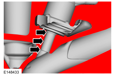
NOTE: Valve guides tend to wear in an hourglass pattern. The ball gauge can be inserted into the combustion chamber side of the valve guide, if necessary.
-
Use a ball gauge to determine the inside diameter of
the valve guides in 2 directions at the top, middle and bottom of the
valve guide.
-
Measure the ball gauge with a micrometer.
-
If the valve guide is not within specifications, install a new cylinder head assembly.
-
Use a ball gauge to determine the inside diameter of
the valve guides in 2 directions at the top, middle and bottom of the
valve guide.
 |
 General Procedures - Spark Plug Inspection
Inspection
NOTE:
Dropped spark plugs should always be discarded.
Unfired
An unfired spark plug should appear very clean
with a pure nickel finish to the threads and ground strap...
 General Procedures - Valve Stem Diameter
Check
NOTE:
Refer to the appropriate Section 303-01 for the specification.
Measure the diameter of each intake and exhaust valve
stem at the points shown...
Other information:
Ford Ecosport 2014-2026 Service and Repair Manual: Diagnosis and Testing - Pinpoint Test - DTC: B, Vehicles With: Rear Seat Side Airbag
B0002:11, B0002:12, B0002:13 and B0002:1A Refer to Wiring Diagrams Cell 46 for schematic and connector information. Normal Operation and Fault Conditions The RCM continuously monitors the driver airbag stage 2 circuits for the following faults: Resistance out of range Unexpected voltage Short to ground Faulted driver airbag If a fault is d..
Ford Ecosport 2014-2026 Service and Repair Manual: Removal and Installation - A-Pillar Outer Panel
Special Tool(s) / General Equipment Resistance Spotwelding Equipment Spherical Cutter Hot Air Gun Air Body Saw 8 mm Drill Bit MIG/MAG Welding Equipment Spot Weld Drill Bit Locking Pliers Removal Depower the SRS . Refer to: Supplemental Restraint System (SRS) Depowering (501-20B Supplemental Restraint System,..
Categories
- Manuals Home
- 2nd Gen Ford Ecosport Service Manual (2014 - 2026)
- Body and Paint
- Description and Operation - Evaporative Emissions - System Operation and Component Description
- Automatic Transmission - 6-Speed Automatic Transmission – 6F35
- Removal and Installation - Blower Motor
- Removal and Installation - Body Control Module (BCM)
Removal and Installation - Wheel Knuckle Bushing
Special Tool(s) / General Equipment
Hydraulic PressRemoval
NOTE: Removal steps in this procedure may contain installation details.
Remove the wheel knuckle.Refer to: Wheel Knuckle - Vehicles With: Rear Drum Brakes (204-02B Rear Suspension - AWD, Removal and Installation).
Remove the rear toe adjustment retainers and remove the wheel knuckle mounting bracket.
Torque:
Stage 1: 177 lb.in (20 Nm)
Stage 2: 76 lb.ft (103 Nm)
Copyright © 2026 www.foecosport2.com