Ford Ecosport: Roof Sheet Metal Repairs / Removal and Installation - Roof Reinforcement
Special Tool(s) / General Equipment
| Resistance Spotwelding Equipment | |
| Spot Weld Drill Bit | |
| Locking Pliers |
Materials
| Name | Specification |
|---|---|
| Seam Sealer TA-2-B, 3M™ 08308, LORD Fusor® 803DTM |
- |
Removal
NOTE: Factory welds may be substituted with resistance or metal inert gas (MIG) plug welds. Resistance welds may not be placed directly over original location. They must be placed adjacent to original location and match factory welds in quantity. Metal inert gas (MIG) plug welds must equal factory welds in both location and quantity.
NOTE: Adequately protect all adjacent areas against cutting, grinding and welding procedures.
-
Depower the SRS .
Refer to: Supplemental Restraint System (SRS) Depowering (501-20B Supplemental Restraint System, General Procedures).
-
If required:
Dimensionally restore the vehicle to pre-damaged condition.
Refer to: Body and Frame (501-26 Body Repairs - Vehicle Specific Information and Tolerance Checks, Description and Operation).
-
Remove the roof.
Refer to: Roof Panel (501-28 Roof Sheet Metal Repairs, Removal and Installation).
-
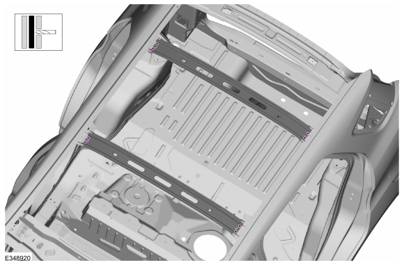
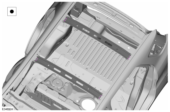
Remove the welds.
Use the General Equipment: Spot Weld Drill Bit
 |
-
NOTE: Pay particular attention to the location of adhesives and sealers to aid in installation.
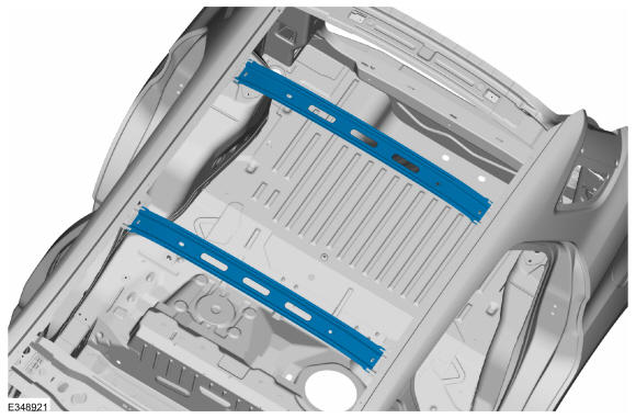
Remove the roof reinforcement.
 |
Installation
NOTE: Factory welds may be substituted with resistance or metal inert gas (MIG) plug welds. Resistance welds may not be placed directly over original location. They must be placed adjacent to original location and match factory welds in quantity. Metal inert gas (MIG) plug welds must equal factory welds in both location and quantity.
NOTE: Adequately protect all adjacent areas against cutting, grinding and welding procedures.
-
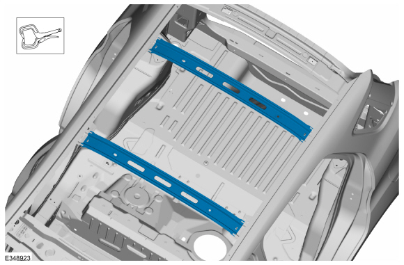
Install, properly position and clamp the roof reinforcement.
Use the General Equipment: Locking Pliers
 |
-
Install the welds.
Use the General Equipment: Resistance Spotwelding Equipment
 |
-
Metal finish as required using typical metal finishing techniques.
-
Sealing work:
All areas must be sealed to production level.
Material: Seam Sealer / TA-2-B, 3M™ 08308, LORD Fusor® 803DTM
-
Refinish the repair using a Ford approved paint system.
-
Restore corrosion protection.
Refer to: Corrosion Prevention (501-25 Body Repairs - General Information, General Procedures).
-
Install the roof panel.
Refer to: Roof Panel (501-28 Roof Sheet Metal Repairs, Removal and Installation).
-
Repower the SRS .
Refer to: Supplemental Restraint System (SRS) Repowering (501-20B Supplemental Restraint System, General Procedures).
 Removal and Installation - Roof Rear Frame
Special Tool(s) /
General Equipment
Resistance Spotwelding Equipment
Spot Weld Drill Bit
Locking Pliers
Materials
Name
Specification
Seam SealerTA-2-B, 3M™ 08308, LORD Fusor® 803DTM
-
Removal
NOTE:
Factory welds may be substituted with resistance or metal
inert gas (MIG) plug welds...
 Removal and Installation - Roof Side Rail - Center
Special Tool(s) /
General Equipment
Resistance Spotwelding Equipment
Spherical Cutter
Hot Air Gun
Air Body Saw
8 mm Drill Bit
MIG/MAG Welding Equipment
Spot Weld Drill Bit
Locking Pliers
Materials
Name
Specification
Seam SealerTA-2-B, 3M™ 08308, LORD Fusor® 803DTM
-
Flexible Foam Repair3M�..
Other information:
Ford Ecosport 2014-2026 Service and Repair Manual: Diagnosis and Testing - Pinpoint Test - DTC: L, Vehicles With: Rear Seat Side Airbag
B007F:11, B007F:12, B007F:13, B007F:1A Refer to Wiring Diagrams Cell 46 for schematic and connector information. Normal Operation and Fault Conditions The RCM continuously monitors the passenger seatbelt retractor pretensioner circuits for the following faults: Resistance out of range Unexpected voltage Short to ground Faulted passenger seatbelt r..
Ford Ecosport 2014-2026 Service and Repair Manual: General Procedures - Parking Brake Cable Adjustment - Vehicles With: Rear Disc Brakes
Adjustment Apply the brake pedal 2 times. Detach the parking brake control boot and position the boot upward on the handle. Remove and discard the lock nut. Loosen the parking brake cable adjustment nut 5 full turns. Wi..
Categories
- Manuals Home
- 2nd Gen Ford Ecosport Service Manual (2014 - 2026)
- Removal and Installation - Evaporative Emission Canister Purge Valve
- Diagnosis and Testing - Evaporative Emissions
- Removal and Installation - Blower Motor
- Removal and Installation - Front Seat
- Diagnosis and Testing - Body Control Module (BCM)
Removal and Installation - Front Brake Flexible Hose
Removal
Remove the wheel and tire.Refer to: Wheel and Tire (204-04A Wheels and Tires, Removal and Installation).
Remove the brake flexible hose bracket bolt.
Disconnect the brake tube fitting and remove the brake hose clip.
Loosen the brake hose fitting and remove the brake flexible hose.