Ford Ecosport: Anti-Lock Brake System (ABS) and Stability Control / Removal and Installation - Hydraulic Control Unit (HCU)
Ford Ecosport 2014-2026 Service and Repair Manual / Brake System / Anti-Lock Brake System (ABS) and Stability Control / Removal and Installation - Hydraulic Control Unit (HCU)
Removal
NOTE: Removal steps in this procedure may contain installation details.
NOTE: A new HCU is equipped with a new ABS module.
-
NOTE: The PMI process must begin with the current ABS module installed. If the current ABS module does not respond to the diagnostic scan tool, the tool may prompt for As-Built Data as part of the repair.
Using a diagnostic scan tool, begin the PMI process for the ABS module following the on-screen instructions.
-
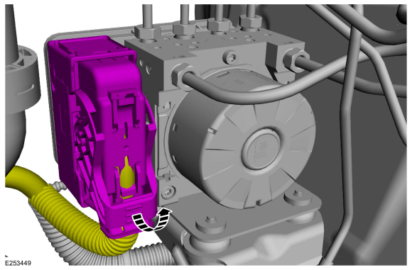
Disconnect the ABS module electrical connector.
 |
-
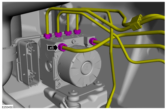
NOTICE: Make sure that all openings are sealed.
Disconnect the brake tube fittings.
Torque: 159 lb.in (18 Nm)
 |
-
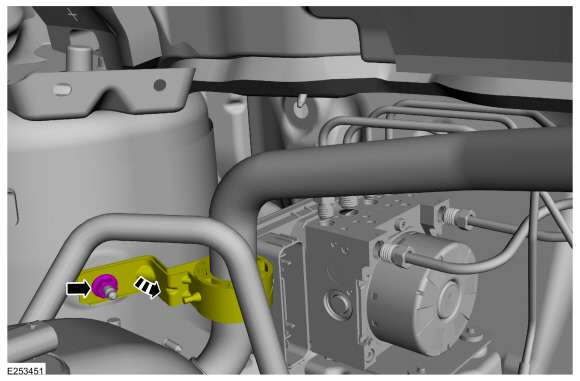
If equipped.
Remove the nut and detach the evaporator inlet and outlet manifold bracket.
Torque: 27 lb.in (3 Nm)
 |
-
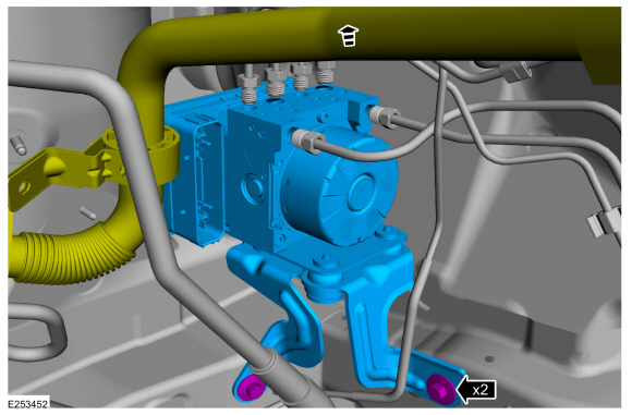
Remove the bolts and pulling slightly upwards on the
evaporator inlet and outlet manifold (if equipped), remove the HCU and ABS module assembly.
Torque: 177 lb.in (20 Nm)
 |
-
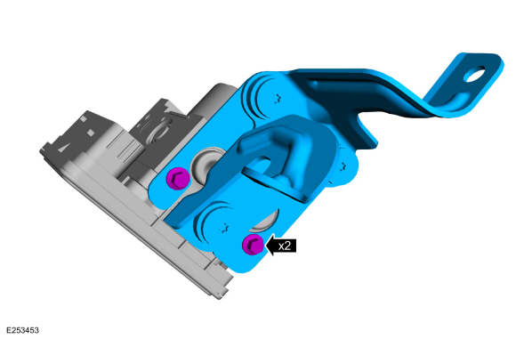
NOTE: This step is only necessary if a new HCU is being installed.
Remove the bolts and the HCU bracket.
Torque: 89 lb.in (10 Nm)
 |
Installation
-
To install, reverse the removal procedure.
-
Using a diagnostic scan tool, complete the PMI process for the ABS module following the on-screen instructions.
-
Carry out the ABS Calibration, Accelerometer Calibration, HCU
Coil Solenoid Calibration, Brake Master Cylinder Pressure Transducer
Calibration and the Brake System Pressure Bleeding using the scan tool
and following the diagnostic scan tool on-screen instructions.
 Removal and Installation - Front Wheel Speed Sensor
Removal
NOTE:
Removal steps in this procedure may contain installation details.
NOTE:
Note the position of the front wheel speed sensor before removal...
 Removal and Installation - Rear Wheel Speed Sensor - 4WD
Removal
NOTE:
Removal steps in this procedure may contain installation details.
NOTE:
Note the position of the rear wheel speed sensor before removal...
Other information:
Ford Ecosport 2014-2026 Service and Repair Manual: Description and Operation - Interior Lighting - System Operation and Component Description
System Operation System Diagram - Interior Lighting Item Description 1 BCM 2 GWM 3 HS-CAN1 4 Door ajar switches 5 Front interior lamp 6 Rear interior lamp 7 Cargo lamp 8 Footwell lamps 9 Front door ambient lighting lamps 10 Cup holder ambient lighti..
Ford Ecosport 2014-2026 Service and Repair Manual: Description and Operation - Intake Air Distribution and Filtering - System Operation and Component Description
System Operation Adaptive Airflow Some vehicles equipped with electronic throttle control (ETC) have an adaptive airflow strategy that allows the PCM to correct for changes in the airflow. During idle, the PCM monitors the throttle angle and airflow. If the airflow is determined to be less than expected, the PCM adjusts the throttle angle to compensate. The PCM only learns the..
Categories
- Manuals Home
- 2nd Gen Ford Ecosport Service Manual (2014 - 2026)
- Body and Paint
- General Procedures - Battery Charging
- Removal and Installation - Blower Motor
- Removal and Installation - Front Seat
- Removal and Installation - Body Control Module (BCM)
Removal and Installation - Oil Pressure Switch
Materials
Name Specification Motorcraft® Thread Sealant with PTFETA-24-B WSK-M2G350-A2
Removal
NOTE: Removal steps in this procedure may contain installation details.
With the vehicle in NEUTRAL, position it on a hoist.Refer to: Jacking and Lifting - Overview (100-02 Jacking and Lifting, Description and Operation).
If equipped, remove the bolts and the underbody shield.
Copyright © 2026 www.foecosport2.com