Ford Ecosport: Electronic Engine Controls - 2.0L Duratec-HE (129kW/175PS) / Removal and Installation - Catalyst Monitor Sensor
Ford Ecosport 2014-2026 Service and Repair Manual / Engine / Electronic Engine Controls - 2.0L Duratec-HE (129kW/175PS) / Removal and Installation - Catalyst Monitor Sensor
Special Tool(s) / General Equipment
 |
303-476
(T94P-9472-A)
Socket, Exhaust Gas Oxygen Sensor TKIT-1994-LM/M TKIT-1994-F TKIT-1994-FLM/FM |
Materials
| Name | Specification |
|---|---|
| Motorcraft® High Temperature Nickel Anti-Seize Lubricant XL-2 |
- |
| Motorcraft® Penetrating and Lock Lubricant XL-1 |
- |
| Motorcraft® Silicone Brake Caliper Grease and Dielectric Compound XG-3-A |
ESA-M1C200-A ESE-M1C171-A |
Removal
-
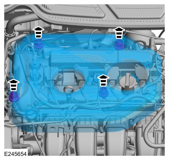
Remove the engine appearance cover.
 |
-
With the vehicle in NEUTRAL, position it on a hoist.
Refer to: Jacking and Lifting - Overview (100-02 Jacking and Lifting, Description and Operation).
-
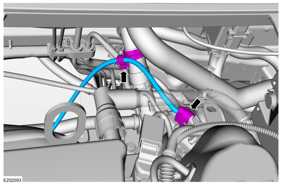
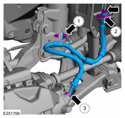
Disconnect the catalyst monitor sensor electrical connector and detach the wiring harness retainer.
 |
-
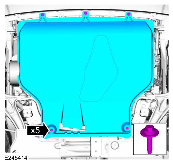
If equipped, remove the bolts and the underbody shield.
 |
-
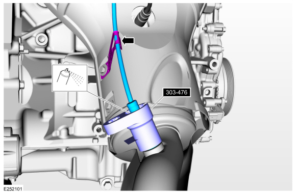
Remove the catalyst monitor sensor.
Use Special Service Tool: 303-476 (T94P-9472-A) Socket, Exhaust Gas Oxygen Sensor.
Material: Motorcraft® Penetrating and Lock Lubricant / XL-1
 |
Installation
-
Calculate the correct torque wrench setting for the
following torque. Refer to Torque Wrench Adapter formula in the Apex.
Install the catalyst monitor sensor.
Use Special Service Tool: 303-476 (T94P-9472-A) Socket, Exhaust Gas Oxygen Sensor.
Material: Motorcraft® High Temperature Nickel Anti-Seize Lubricant / XL-2
Torque: 35 lb.ft (48 Nm)
 |
-
Install the engine undershield and the retainers.
|
-
Connect the catalyst monitor sensor electrical connector and attach the wiring harness retainer.
|
-
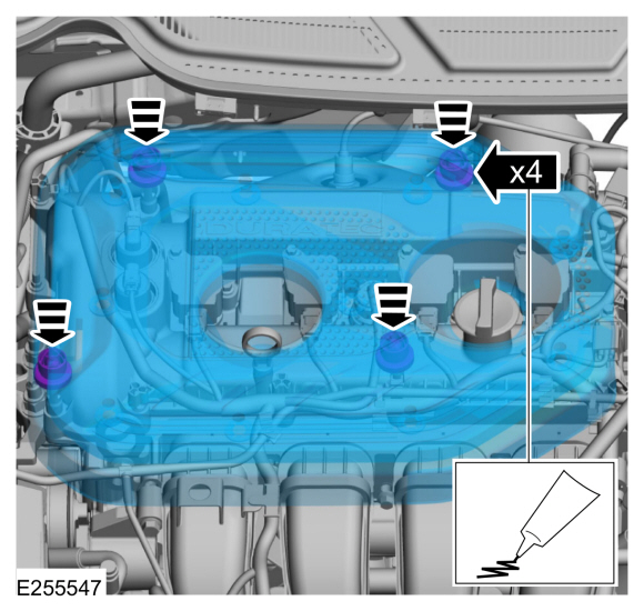
NOTE: Lubricating the grommets with silicone grease will aid in the installation of the cover
-
Lubricate each grommet with silicone grease. Lubricate each grommet with silicone grease.
Material: Motorcraft® Silicone Brake Caliper Grease and Dielectric Compound / XG-3-A (ESA-M1C200-A) (ESE-M1C171-A)
-
Position the engine appearance cover onto engine with the grommets aligned with the studs.
-
Press down on the engine appearance cover at each grommet location to attach the grommets onto the studs.
-
Lubricate each grommet with silicone grease. Lubricate each grommet with silicone grease.
 |
 Removal and Installation - Camshaft Position (CMP) Sensor
Materials
Name
Specification
Engine Oil - SAE 5W-20 - Synthetic Blend Motor OilXO-5W20-Q1SP
WSS-M2C945-B1
Removal
NOTE:
Removal steps in this procedure may contain installation details...
 Removal and Installation - Crankshaft Position (CKP) Sensor
Special Tool(s) /
General Equipment
303-1521Alignment Tool, Crankshaft Position SensorTKIT-2010C-FLM
303-507Timing Peg, Crankshaft TDCTKIT-2001N-FLMTKIT-2001N-ROW
Ford Diagnostic Equipment
Removal
NOTE:
Do not loosen or remove the crankshaft pulley bolt without
first installing the special tools as instructed in this procedure...
Other information:
Ford Ecosport 2014-2026 Service and Repair Manual: Disassembly and Assembly - Wheel and Tire
Special Tool(s) / General Equipment Wooden Block DISASSEMBLY NOTICE: Failure to follow the instructions below may result in damage to the TPMS . NOTICE: The TPMS sensor is mounted to the valve stem. Removal of the valve stem requires dismounting the tire from the wheel and removal of the TPMS sensor...
Ford Ecosport 2014-2026 Service and Repair Manual: Removal and Installation - Air Deflector
Special Tool(s) / General Equipment Flat-Bladed Screwdriver Removal NOTE: Removal steps in this procedure may contain installation details. Place the roof opening panel glass in the fully OPEN position. NOTE: LH side shown, RH side similar...
Categories
- Manuals Home
- 2nd Gen Ford Ecosport Service Manual (2014 - 2026)
- Description and Operation - Evaporative Emissions - System Operation and Component Description
- Description and Operation - Jacking and Lifting - Overview
- Removal and Installation - Fuel Pump and Sender Unit
- Removal and Installation - Front Seat
- Removal and Installation - Body Control Module (BCM)
Removal and Installation - Front Brake Flexible Hose
Removal
Remove the wheel and tire.Refer to: Wheel and Tire (204-04A Wheels and Tires, Removal and Installation).
Remove the brake flexible hose bracket bolt.
Disconnect the brake tube fitting and remove the brake hose clip.
Loosen the brake hose fitting and remove the brake flexible hose.
Copyright © 2026 www.foecosport2.com