Ford Ecosport: Battery, Mounting and Cables / Removal and Installation - Battery
Ford Ecosport 2014-2026 Service and Repair Manual / Battery and Charging System / Battery, Mounting and Cables / Removal and Installation - Battery
Removal
NOTE: Removal steps in this procedure may contain installation details.
-
Disconnect the battery.
Refer to: Battery Disconnect and Connect (414-01 Battery, Mounting and Cables, General Procedures).
-
-
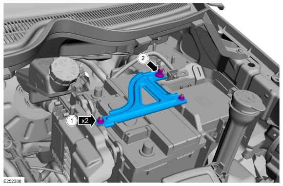
Remove the battery hold-down bracket nuts.
Torque: 62 lb.in (7 Nm)
-
Remove the nut and the battery hold-down bracket.
Torque: 62 lb.in (7 Nm)
-
Remove the battery hold-down bracket nuts.
 |
-
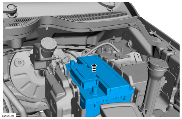
Remove the battery.
 |
Installation
-
To install, reverse the removal procedure.
-
NOTICE: When installing a new battery it may be necessary to adjust the spacer inside the battery tray to prevent battery movement.
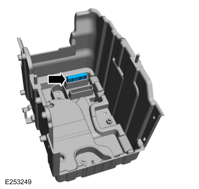
Position the battery. If necessary, adjust the spacer inside the battery tray to prevent movement of the battery.
 |
-
If installing a new battery, use the scan tool to carry
out the Battery Monitoring System (BMS) reset after the battery is
connected.
 General Procedures - Battery Drain Check
Check
NOTE:
No factory-equipped vehicle should have more than a 25 mA
(0.025 amp) – 50 mA (0.050) draw depending on the vehicle's accessories...
 Removal and Installation - Battery Cables - 2.0L Duratec-HE (125kW/170PS) – MI4
Removal
NOTE:
The starter and generator electrical connector and
terminals are integrated into the engine wiring harness and the battery
positive terminal is integrated into the Battery Junction Box (BJB)...
Other information:
Ford Ecosport 2014-2026 Service and Repair Manual: Diagnosis and Testing - Pinpoint Test - DTC: S, Vehicles With: Rear Seat Side Airbag
B11D8:11, B11D8:12, B11D8:13 Refer to Wiring Diagrams Cell 46 for schematic and connector information. Normal Operation and Fault Conditions The RCM transmits an event notification signal which communicates fuel cutoff status and SRS deployment status to the BCM ...
Ford Ecosport 2014-2026 Service and Repair Manual: General Procedures - Engine Noise Identification and Location
NOTE: This procedure uses multiple tools/methods to help locate the source of engine noise. It may be necessary to repeatedly compare the sound between the tools/methods to help locate the source of the noise. NVH symptoms should be identified using the diagnostic tools and techniques that are available...
Categories
- Manuals Home
- 2nd Gen Ford Ecosport Service Manual (2014 - 2026)
- Removal and Installation - Evaporative Emission Canister Purge Valve
- Removal and Installation - Body Control Module (BCM)
- Description and Operation - Jacking and Lifting - Overview
- Removal and Installation - Front Seat
- General Procedures - Transmission Fluid Level Check
Removal and Installation - Brake Disc Shield
Removal
NOTE: Removal steps in this procedure may contain installation details.
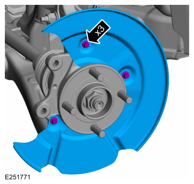
Remove the brake disc.Refer to: Brake Disc (206-03 Front Disc Brake, Removal and Installation).
Remove the bolts and brake disc.
Torque: 80 lb.in (9 Nm)
Copyright © 2026 www.foecosport2.com