Ford Ecosport: Side Panel Sheet Metal Repairs / Removal and Installation - B-Pillar Outer Panel
Ford Ecosport 2014-2026 Service and Repair Manual / Body and Paint / Side Panel Sheet Metal Repairs / Removal and Installation - B-Pillar Outer Panel
Special Tool(s) / General Equipment
| Resistance Spotwelding Equipment | |
| Hot Air Gun | |
| Air Body Saw | |
| MIG/MAG Welding Equipment | |
| Spot Weld Drill Bit | |
| Locking Pliers |
Materials
| Name | Specification |
|---|---|
| Metal Bonding Adhesive TA-1, TA-1-B, 3M™ 08115, LORD Fusor® 108B, Henkel Teroson EP 5055 |
- |
Removal
-
Depower the SRS.
Refer to: Supplemental Restraint System (SRS) Depowering (501-20B Supplemental Restraint System, General Procedures).
-
-
Remove B-pillar trim panel.
Refer to: B-Pillar Trim Panel (501-05 Interior Trim and Ornamentation, Removal and Installation).
-
Remove rocker panel moulding.
Refer to: Rocker Panel Moulding (501-08 Exterior Trim and Ornamentation, Removal and Installation).
-
Remove front seat.
Refer to: Front Seat (501-10A Front Seats, Removal and Installation).
-
Remove rear door.
Refer to: Rear Door (501-03 Body Closures, Removal and Installation).
-
Reposition the carpeting and the wiring harness away from the working area.
-
Remove B-pillar trim panel.
-
Remove the front door striker and rear door hinges on the body.
 |
-
-
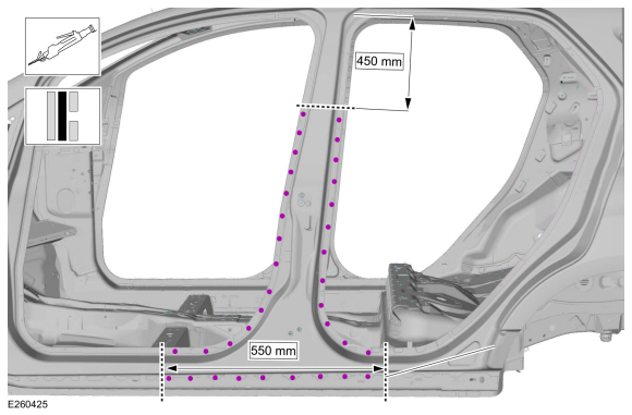
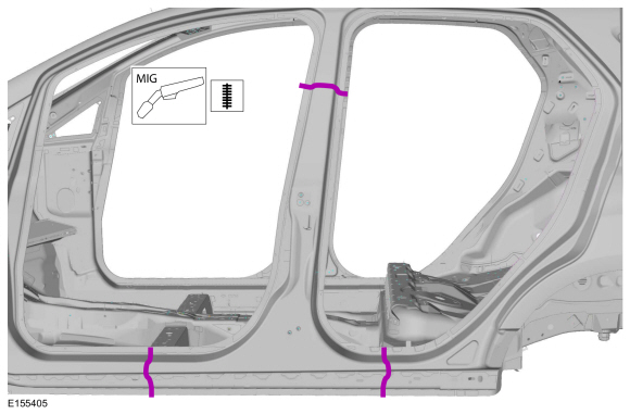
Measure and cut the B-pillar outer panel.
Use the General Equipment: Air Body Saw
Use the General Equipment: Spot Weld Drill Bit
-
Measure and cut the B-pillar outer panel.
 |
-
NOTE: Pay particular attention to the location of sealer and adhesive to aid in installation.
-
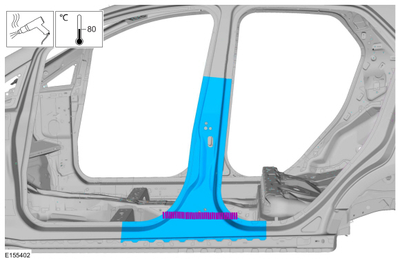
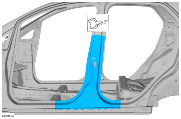
Break the adhesive bond and remove the B-pillar outer panel.
Use the General Equipment: Hot Air Gun
-
Break the adhesive bond and remove the B-pillar outer panel.
 |
Installation
-
NOTE: Sealer or adhesive must not be applied in welding zones. Areas which were bonded or sealed needs to be thoroughly sealed afterwards.
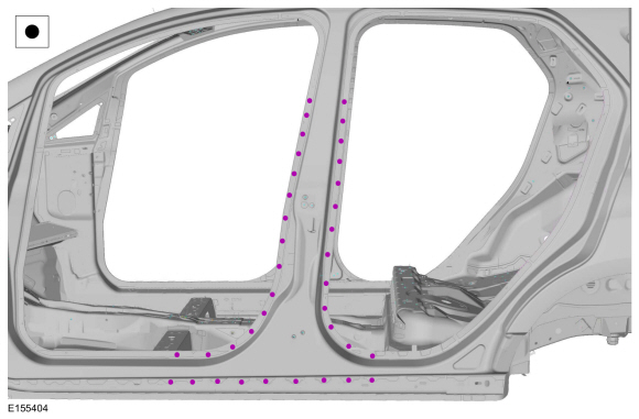
Install adhesive in areas noted during removal.
Material: Metal Bonding Adhesive / TA-1, TA-1-B, 3M™ 08115, LORD Fusor® 108B, Henkel Teroson EP 5055
-
-
Install B-pillar outer panel and clamp in position.
Use the General Equipment: Locking Pliers
-
Install B-pillar outer panel and clamp in position.
 |
-
-
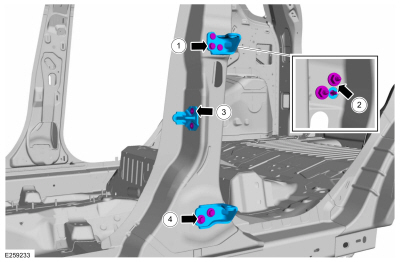
Install welds.
Use the General Equipment: Resistance Spotwelding Equipment
-
Install welds.
 |
-
-
Seam weld sectioning joints.
Use the General Equipment: MIG/MAG Welding Equipment
-
Seam weld sectioning joints.
 |
-
Metal finish as required using typical metal finishing techniques and materials.
-
All seams must be sealed to production level.
-
Refinish the entire repair using a Ford approved paint system.
-
Restore corrosion protection.
Refer to: Corrosion Prevention (501-25 Body Repairs - General Information, General Procedures).
-
-
Tighten the rear door upper hinge screw.
Torque: 89 lb.in (10 Nm)
-
Tighten the rear door upper hinge nuts.
Torque: 17 lb.ft (23 Nm)
-
Install the bolts and front door striker.
Torque: 177 lb.in (20 Nm)
-
Install the bolts and rear door hinge.
Torque: 26 lb.ft (35 Nm)
-
Tighten the rear door upper hinge screw.
 |
-
-
Install the B-pillar trim panel.
Refer to: B-Pillar Trim Panel (501-05 Interior Trim and Ornamentation, Removal and Installation).
-
Install the rocker panel moulding.
Refer to: Rocker Panel Moulding (501-08 Exterior Trim and Ornamentation, Removal and Installation).
-
Install the front seat.
Refer to: Front Seat (501-10A Front Seats, Removal and Installation).
-
Install the rear door.
Refer to: Rear Door (501-03 Body Closures, Removal and Installation).
-
Reposition the carpeting and the wiring harness away from the working area.
-
Install the B-pillar trim panel.
-
Repower the SRS
Refer to: Rear Door Alignment (501-03 Body Closures, General Procedures).
 Removal and Installation - B-Pillar and Reinforcement
Special Tool(s) /
General Equipment
Resistance Spotwelding Equipment
Spherical Cutter
Hot Air Gun
Air Body Saw
8 mm Drill Bit
MIG/MAG Welding Equipment
Spot Weld Drill Bit
Locking Pliers
Removal
NOTICE:
Protect the vehicle interior from damage during repair process...
 Removal and Installation - Side Panel
Special Tool(s) /
General Equipment
Resistance Spotwelding Equipment
Spherical Cutter
Hot Air Gun
Air Body Saw
8 mm Drill Bit
MIG/MAG Welding Equipment
Spot Weld Drill Bit
Locking Pliers
Materials
Name
Specification
Metal Bonding AdhesiveTA-1, TA-1-B, 3M™ 08115, LORD Fusor® 108B, Henkel Teroson EP 5055
-&n..
Other information:
Ford Ecosport 2014-2026 Service and Repair Manual: Removal and Installation - Start Inhibit Switch
Removal NOTICE: Make sure that the clutch pedal remains in the rest position. NOTE: Removal steps in this procedure may contain installation details. NOTE: Left hand drive (LHD) shown, right hand drive (RHD) similar. Disconnect the electrical connector and remove the start inhibit switch. Installation NOTICE: ..
Ford Ecosport 2014-2026 Service and Repair Manual: Removal and Installation - Ignition Switch
Removal NOTE: Removal steps in this procedure may contain installation details. Remove the steering column shrouds. Refer to: Steering Column Shrouds (501-05 Interior Trim and Ornamentation, Removal and Installation). Disconnect the ignition switch electrical connector. Release the ignition swit..
Categories
- Manuals Home
- 2nd Gen Ford Ecosport Service Manual (2014 - 2026)
- Diagnosis and Testing - Evaporative Emissions
- Removal and Installation - Front Seat
- Body and Paint
- Removal and Installation - Blower Motor
- Removal and Installation - Catalytic Converter
Description and Operation - Health and Safety Precautions
General Service Warnings
Review carefully the information below before beginning any repair. Following these warnings is a list of specific system warnings that must be reviewed before beginning work on any listed system.
 WARNING:
Wear eye and ear protection when servicing a vehicle.
Failure to follow this instruction may result in serious personal
injury.
WARNING:
Wear eye and ear protection when servicing a vehicle.
Failure to follow this instruction may result in serious personal
injury.
Copyright © 2026 www.foecosport2.com