Ford Ecosport: Brake System - General Information / General Procedures - Component Bleeding
Special Tool(s) / General Equipment
| Master Cylinder Bleeding Set |
Bleeding
NOTICE: If the fluid is spilled on the paintwork, the affected area must be immediately washed down with cold water.
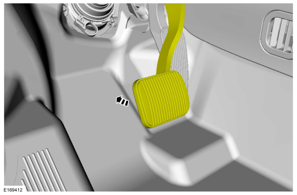
Master Cylinder
NOTE: When a new brake master cylinder has been installed, it should be primed to prevent air from entering the system.
-
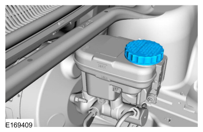
NOTE: Make sure the area around the master cylinder cap is clean and free of foreign material.
Remove the brake fluid reservoir cap.
 |
-
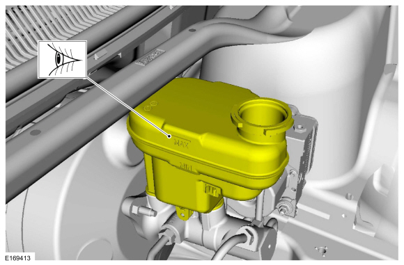
Fill the reservoir with clean, specified brake fluid.
Refer to: Specifications (206-00 Brake System - General Information, Specifications).
 |
-
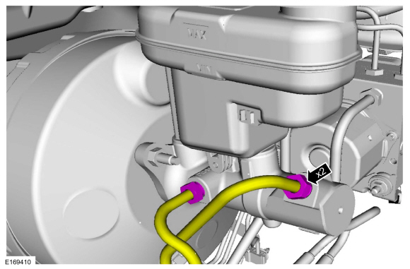
Loosen and remove the brake tube fittings.
 |
-
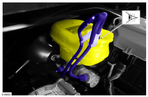
Install the master cylinder bleeding set.
Use the General Equipment: Master Cylinder Bleeding Set
 |
-
Have an assistant pump the brake pedal slowly until clear bubble free fluid flows from the brake tubes.
 |
-
Remove the master cylinder bleeding set.
Remove the General Equipment: Master Cylinder Bleeding Set
|
-
Tighten the brake tube fittings.
Refer to: Specifications (206-00 Brake System - General Information, Specifications).
|
-
Fill the reservoir with clean, specified brake fluid.
Refer to: Specifications (206-00 Brake System - General Information, Specifications).
|
-
Refer to: Brake System Pressure Bleeding - Vehicles With: Vacuum Brake Booster (206-00)
.
Brake Caliper, Wheel Cylinder, Brake Hose or Brake Tube
-
NOTE: Pressure bleeding the brake system is required anytime a hydraulic brake system component has been disconnected.
Refer to: Brake System Pressure Bleeding - Vehicles With: Vacuum Brake Booster (206-00) .
 General Procedures - Brake System Pressure Bleeding
Special Tool(s) /
General Equipment
Brake/Clutch System Pressure Bleeder/Filler
Fluid Container
Bleeding
All vehicles
NOTICE:
If the fluid is spilled on the paintwork, the affected area must be immediately washed down with cold water...

Other information:
Ford Ecosport 2014-2026 Service and Repair Manual: Diagnosis and Testing - Rear View Mirrors
Refer to Wiring Diagrams Cell 124 for schematic and connector information. Symptom Chart(s) Symptom Chart: Rear View Mirrors - Exterior Diagnostics in this manual assume a certain skill level and knowledge of Ford-specific diagnostic practices. NOTE: Clean the entire mirror assembly and glass to assist in verification of the customer concern and/or impa..
Ford Ecosport 2014-2026 Service and Repair Manual: Removal and Installation - Rear Wheel Speed Sensor - 4WD
Removal NOTE: Removal steps in this procedure may contain installation details. NOTE: Note the position of the rear wheel speed sensor before removal. Remove the wheel and tire. Refer to: Wheel and Tire (204-04A Wheels and Tires, Removal and Installation). Disconnect the electrical connector and detach the wiring retainers. ..
Categories
- Manuals Home
- 2nd Gen Ford Ecosport Service Manual (2014 - 2026)
- Removal and Installation - Catalytic Converter
- Removal and Installation - Roof Rail
- Removal and Installation - Evaporative Emission Canister Purge Valve
- Removal and Installation - Blower Motor
- Engine
Removal and Installation - Front Stabilizer Bar
Special Tool(s) / General Equipment
Tie Rod End Remover Transmission JackRemoval
NOTICE: Suspension fasteners are critical parts that affect the performance of vital components and systems. Failure of these fasteners may result in major service expense. Use the same or equivalent parts if replacement is necessary. Do not use a replacement part of lesser quality or substitute design. Tighten fasteners as specified.
NOTE: Removal steps in this procedure may contain installation details.
NOTICE: Disconnect the b