Ford Ecosport: Bumpers / Disassembly and Assembly - Rear Bumper Cover
Ford Ecosport 2014-2026 Service and Repair Manual / Body and Paint / Bumpers / Disassembly and Assembly - Rear Bumper Cover
DISASSEMBLY
All vehicles
-
Remove the rear bumper cover.
Refer to: Rear Bumper Cover (501-19 Bumpers, Removal and Installation).
-
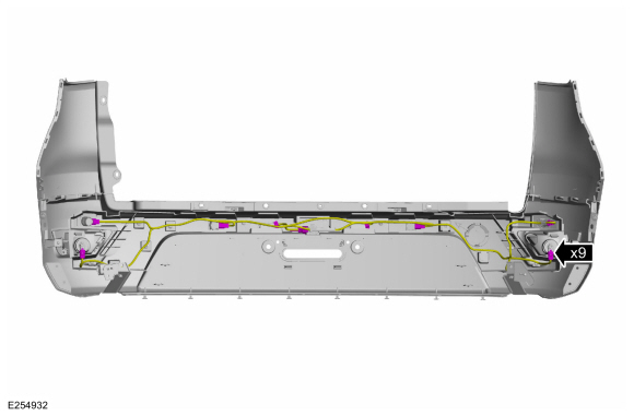
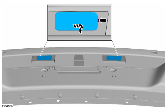
Disconnect the rear bumper cover harness electrical connectors.
 |
-
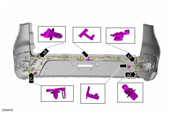
Separate the wire harness guides and remove the rear bumper cover wire harness.
 |
Vehicles equipped with rear parking aid sensors
-
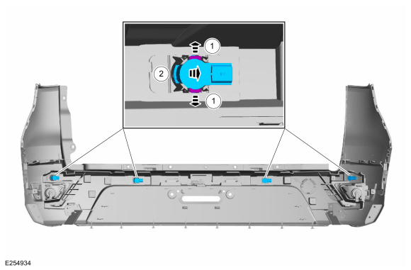
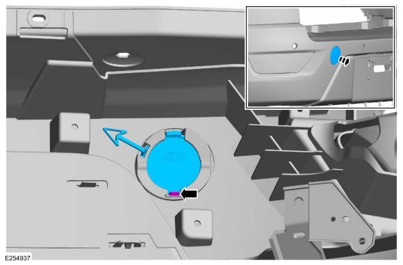
NOTE: Make sure that the isolator rings are installed correctly while installing the sensors.
Remove the rear parking aid sensors.
-
Release the tabs.
-
Separate the sensor from the bracket.
-
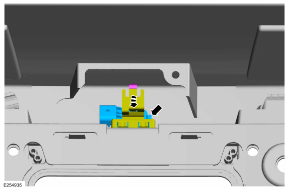
Release the tabs.
 |
Vehicles equipped with rear parking aid camera
-
Release the bracket and remove the rear parking aid camera.
 |
All vehicles
-
If equipped.
Release the tabs and remove the rear licence plate lamp assembly.
 |
-
Release the tab and remove the tow hook cover.
 |
-
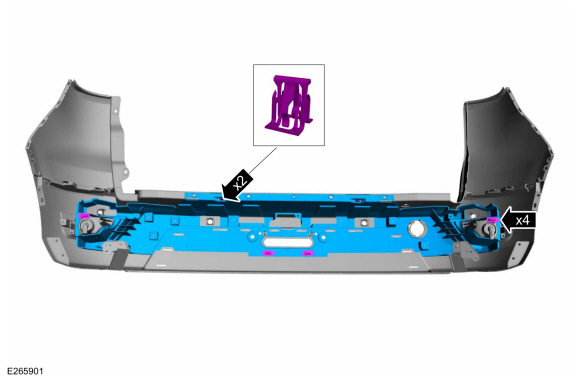
Release the tabs and remove the central bracket.
 |
-
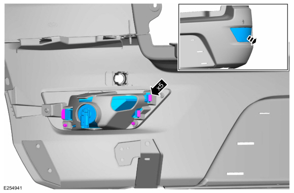
On both sides.
Release the tabs and remove the rear light assembly.
 |
-
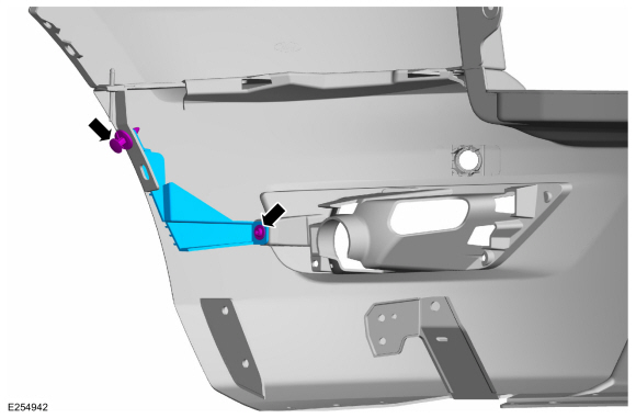
If equipped, on both sides.
Remove the pin-type retainer, the screw and the rear bumper mounting bracket.
 |
-
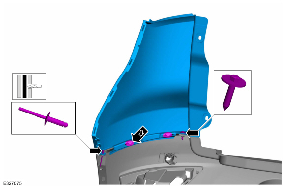
On both sides.
Drill the rivet, remove the screw, release the tabs and remove the side valance.
 |
ASSEMBLY
-
To assemble, reverse the disassembly procedure.
Vehicles equipped with rear parking aid sensors
-
Carry out the azimuth and elevation system checks.
Refer to: Azimuth System Check (413-13A Parking Aid, General Procedures).
Refer to: Elevation System Check (413-13A Parking Aid, General Procedures).
-
If any sensor fails the check, diagnose the sensor fault.
Refer to: Parking Aid (413-13A Parking Aid, Diagnosis and Testing).
 Disassembly and Assembly - Front Bumper Cover
Special Tool(s) /
General Equipment
Hot Air Gun
DISASSEMBLY
Remove the front bumper cover.
Refer to: Front Bumper Cover (501-19 Bumpers, Removal and Installation)...

Other information:
Ford Ecosport 2014-2026 Service and Repair Manual: Removal and Installation - Evaporative Emission Canister
Removal WARNING: Do not smoke, carry lighted tobacco or have an open flame of any type when working on or near any fuel-related component. Highly flammable mixtures may be present and may be ignited. Failure to follow these instructions may result in serious personal injury. WARNING: Do not carry personal electronic devices such as cell phones, pagers or ..
Ford Ecosport 2014-2026 Service and Repair Manual: General Procedures - Engine Noise Identification and Location
NOTE: This procedure uses multiple tools/methods to help locate the source of engine noise. It may be necessary to repeatedly compare the sound between the tools/methods to help locate the source of the noise. NVH symptoms should be identified using the diagnostic tools and techniques that are available. For a list of these techniques, tools, an explanation of their..
Categories
- Manuals Home
- 2nd Gen Ford Ecosport Service Manual (2014 - 2026)
- Diagnosis and Testing - Body Control Module (BCM)
- Removal and Installation - Blower Motor
- General Procedures - Battery Charging
- Diagnosis and Testing - Evaporative Emissions
- Removal and Installation - Evaporative Emission Canister Purge Valve
Description and Operation - Health and Safety Precautions
General Service Warnings
Review carefully the information below before beginning any repair. Following these warnings is a list of specific system warnings that must be reviewed before beginning work on any listed system.
 WARNING:
Wear eye and ear protection when servicing a vehicle.
Failure to follow this instruction may result in serious personal
injury.
WARNING:
Wear eye and ear protection when servicing a vehicle.
Failure to follow this instruction may result in serious personal
injury.
Copyright © 2026 www.foecosport2.com