Ford Ecosport: Horn / Description and Operation - Horn - Component Location
Ford Ecosport 2014-2026 Service and Repair Manual / Instrumentation and Warning Systems / Horn / Description and Operation - Horn - Component Location
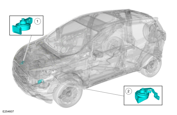
| Item | Description |
|---|---|
| 1 | RH Horn |
| 2 | LH Horn |
 Horn
Horn
..
 Description and Operation - Horn - System Operation and Component Description
System Operation
System Diagram
Item
Description
1
LH Horn
2
RH Horn
3
Horn Relay
4
BCM
5
Clockspring
6
Horn Switch
Horn Operation
The
horn switch consists of 2 sets of contacts separated by springs...
Other information:
Ford Ecosport 2014-2026 Service and Repair Manual: Removal and Installation - Interior Rear Door Handle
Special Tool(s) / General Equipment Interior Trim Remover Removal NOTE: LH side shown, RH side similar. Remove the rear door trim panel. Refer to: Rear Door Trim Panel (501-05 Interior Trim and Ornamentation, Removal and Installation)...
Ford Ecosport 2014-2026 Service and Repair Manual: Removal and Installation - Rear Door Window Regulator Motor
Removal NOTE: Removal steps in this procedure may contain installation details. Remove the rear door window regulator. Refer to: Rear Door Window Regulator (501-11 Glass, Frames and Mechanisms, Removal and Installation). Remove the rear door window regulator motor...
Categories
- Manuals Home
- 2nd Gen Ford Ecosport Service Manual (2014 - 2026)
- Engine
- Body and Paint
- Removal and Installation - Starter Motor
- Removal and Installation - Evaporative Emission Canister Purge Valve
- Removal and Installation - Rear Bumper
Removal and Installation - Rear Halfshaft Seal
Special Tool(s) / General Equipment
 205-153
(T80T-4000-W)
205-153
(T80T-4000-W)
Handle
 205-990
Installer, Axle Seal
TKIT-2012A-FL
TKIT-2012A-ROW
Copyright © 2026 www.foecosport2.com