Ford Ecosport: Horn / Description and Operation - Horn - System Operation and Component Description
System Operation
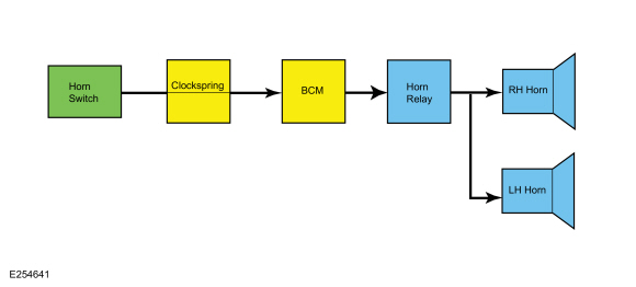
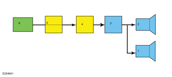
System Diagram
| Item | Description |
|---|---|
| 1 | LH Horn |
| 2 | RH Horn |
| 3 | Horn Relay |
| 4 | BCM |
| 5 | Clockspring |
| 6 | Horn Switch |
Horn Operation
The horn switch consists of 2 sets of contacts separated by springs. The lower set is connected to ground and the upper set is connected to the horn signal circuit. When the driver air bag module is pressed, it pushes down on the upper set of contacts, collapsing the springs and allowing the contacts to touch. When the contacts touch, it completes the circuit and provides the ground signal which is routed through the clockspring to the BCM . The BCM then energizes the horn relay sending voltage to the horn, enabling the horn to sound.
Component Description
Horn
The left and right horns consists of different notes (high and low) attached to a bracket.
Clockspring
The clockspring is the interface between the BCM and the horn switch contacts. It allows the steering wheel to rotate while maintaining circuit integrity with the electrically monitored/activated components mounted to the steering wheel.
BCM
The BCM controls the horn activation based on input from horn switch contacts and other features.
The BCM requires PMI when replaced. Additionally, carry out the parameter reset procedure and program at least 2 keys.

 Diagnosis and Testing - Horn
DTC Chart
Diagnostics in this manual assume a certain skill level and knowledge of Ford-specific diagnostic practices. REFER to: Diagnostic Methods (100-00 General Information, Description and Operation)...
Other information:
Ford Ecosport 2014-2026 Service and Repair Manual: Description and Operation - Electronic Engine Controls - Overview
Overview The EEC system provides optimum control of the engine through the enhanced capability of the powertrain control module (PCM). The EEC system also has an on board diagnostic (OBD) monitoring system with features and functions to meet federal regulations on exhaust emissions...
Ford Ecosport 2014-2026 Service and Repair Manual: Removal and Installation - Oil Pump
Special Tool(s) / General Equipment Oil Drain Equipment Round-Ended Steel Rule Materials Name Specification Motorcraft® Silicone Gasket and SealantTA-30 WSE-M4G323-A4 Removal NOTICE: During engine repair procedures, cleanliness is extremely important...
Categories
- Manuals Home
- 2nd Gen Ford Ecosport Service Manual (2014 - 2026)
- Diagnosis and Testing - Evaporative Emissions
- Removal and Installation - Rear Bumper
- Engine
- Body and Paint
- Description and Operation - Evaporative Emissions - System Operation and Component Description
Removal and Installation - Steering Column Shaft
Removal
NOTE: Removal steps in this procedure may contain installation details.
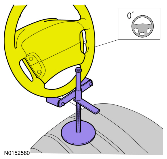
NOTICE: Do not allow the steering column to rotate while the steering column shaft is disconnected or damage to the steering column internal sensor may result.
NOTE: Use a steering wheel holding device (such as Hunter® 28-75-1 or equivalent)
Hold the steering wheel in the straight-ahead position.