Ford Ecosport: Roof Opening Panel / Removal and Installation - Roof Opening Panel Frame
Ford Ecosport 2014-2026 Service and Repair Manual / Body and Paint / Roof Opening Panel / Removal and Installation - Roof Opening Panel Frame
Removal
NOTE: Removal steps in this procedure may contain installation details.
-
Remove the headliner.
Refer to: Headliner (501-05 Interior Trim and Ornamentation, Removal and Installation).
-
-
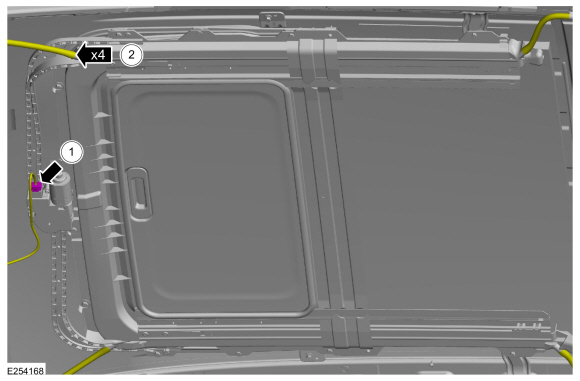
Disconnect the roof opening panel motor electrical connector.
-
Disconnect the roof opening panel drain hoses from the corners of the roof opening panel frame.
-
Disconnect the roof opening panel motor electrical connector.
 |
-
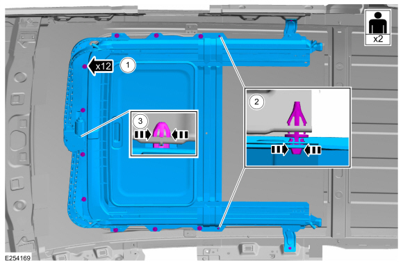
With the help of an assistant.
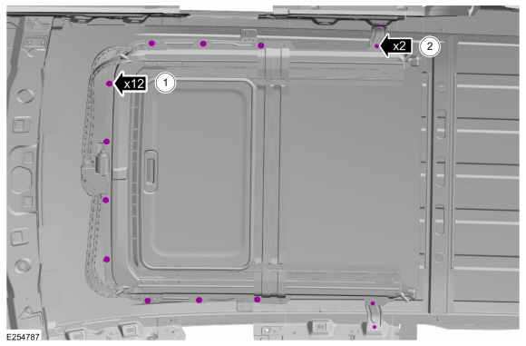
Remove the roof opening panel frame.
-
Remove the roof opening panel frame bolts.
-
Release the retaining clips.
-
Release the front retaining clip and remove the roof opening panel frame.
-
Remove the roof opening panel frame bolts.
 |
-
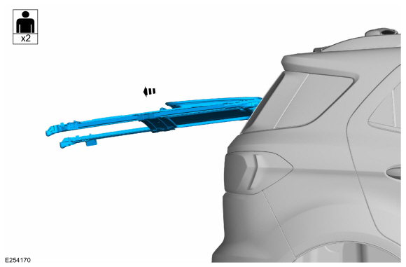
With the help of an assistant.
Remove the roof opening panel frame.
 |
-
On both sides.
Remove the bolt and the roof opening panel bracket.
 |
Installation
-
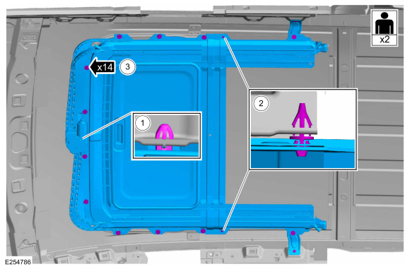
With the help of an assistant.
Install the roof opening panel frame.
-
Attach the front retaining clip.
-
Attach the retaining clips.
-
Tighten the bolts finger tight.
-
Attach the front retaining clip.
 |
-
-
Tighten the roof opening panel frame bolts.
Torque: 53 lb.in (6 Nm)
-
Tighten the roof opening panel frame bracket bolts.
Torque: 80 lb.in (9 Nm)
-
Tighten the roof opening panel frame bolts.
 |
-
-
Connect the roof opening panel motor electrical connector.
-
Connect the roof opening panel drain hoses from the corners of the roof opening panel frame.
-
Connect the roof opening panel motor electrical connector.
|
-
Install the headliner.
Refer to: Headliner (501-05 Interior Trim and Ornamentation, Removal and Installation).
-
Align the roof opening panel.
Refer to: Roof Opening Panel Alignment (501-17 Roof Opening Panel, General Procedures).
-
Initialize the roof opening panel.
Refer to: Power Roof Opening Panel Initialization (501-17 Roof Opening Panel, General Procedures).
 Removal and Installation - Roof Opening Panel Control Switch
Special Tool(s) /
General Equipment
Interior Trim Remover
Removal
NOTE:
Removal steps in this procedure may contain installation details...
 Removal and Installation - Roof Opening Panel Front Drain Hose
Removal
NOTE:
Removal steps in this procedure may contain installation details.
NOTE:
LH side shown, RH side similar.
Remove the headliner...
Other information:
Ford Ecosport 2014-2026 Service and Repair Manual: Description and Operation - Brake and Clutch Systems Health and Safety Precautions
WARNING: EYE CONTACT: Brake fluid contains polyglycol ethers and polyglycols. Avoid contact with the eyes. Wash hands thoroughly after handling. If brake fluid comes into contact with the eyes, flush the eyes with plenty of cold running water for 15 minutes...
Ford Ecosport 2014-2026 Service and Repair Manual: General Procedures - Transmission Fluid Level Check
Materials Name Specification Motorcraft® MERCON® LV Automatic Transmission FluidXT-10-QLVC WSS-M2C938-AMERCON® LV, Check Connect the diagnostic scan tool to the vehicle. Monitor the TFT PID . With the engine running in PARK on a level surface make sure the transmission is at normal operating temperature 85-93° C (185-2..
Categories
- Manuals Home
- 2nd Gen Ford Ecosport Service Manual (2014 - 2026)
- Diagnosis and Testing - Body Control Module (BCM)
- Removal and Installation - Fuel Pump and Sender Unit
- Description and Operation - Jacking and Lifting - Overview
- Removal and Installation - Catalytic Converter
- Removal and Installation - Roof Rail
Removal and Installation - Variable Camshaft Timing (VCT) Unit
Removal
NOTICE: During engine repair procedures, cleanliness is extremely important. Any foreign material, including any material created while cleaning gasket surfaces, that enters the oil passages, coolant passages or the oil pan can cause engine failure.
Remove the timing chain.Refer to: Timing Chain (303-01C Engine - 2.0L Duratec-HE (129kW/175PS), Removal and Installation).
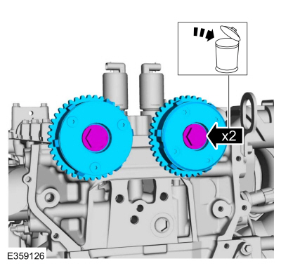
Remove the bolts and VCT units.
Discard the bolts.
Copyright © 2026 www.foecosport2.com