Ford Ecosport: Rear End Sheet Metal Repairs / Removal and Installation - Rear Lamp Mounting Panel
Special Tool(s) / General Equipment
| 8 mm Drill Bit | |
| MIG/MAG Welding Equipment | |
| Spot Weld Drill Bit | |
| Locking Pliers |
Materials
| Name | Specification |
|---|---|
| Seam Sealer TA-2-B, 3M™ 08308, LORD Fusor® 803DTM |
- |
Removal
NOTE: Factory welds may be substituted with resistance or metal inert gas (MIG) plug welds. Resistance welds may not be placed directly over original location. They must be placed adjacent to original location and match factory welds in quantity. Metal inert gas (MIG) plug welds must equal factory welds in both location and quantity.
NOTE: Adequately protect all adjacent areas against cutting, grinding and welding procedures.
NOTE: LH side shown, RH side similar.
-
Remove the Quarter Panel LH.
Refer to: Quarter Panel LH (501-30 Rear End Sheet Metal Repairs, Removal and Installation).
-
Drill out the spot welds.
Use the General Equipment: Spot Weld Drill Bit
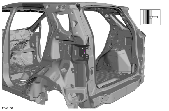 |
-
Remove the rear lamp mounting panel.
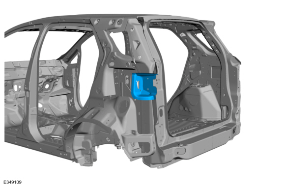 |
Installation
NOTE: LH side shown, RH side similar.
-
Refer to: Joining Techniques (501-25 Body Repairs - General Information, General Procedures).
-
Drill holes in the replacement panel for plug welding.
Use the General Equipment: 8 mm Drill Bit
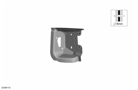 |
-
Install, properly position and clamp the rear lamp mounting panel.
Use the General Equipment: Locking Pliers
 |
-
Install plug welds.
Use the General Equipment: MIG/MAG Welding Equipment
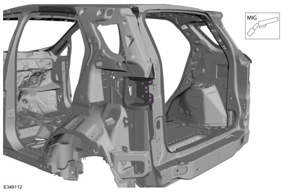 |
-
Finish repair area using typical metal finishing techniques.
-
Sealing work: All areas must be sealed to production level.
Material: Seam Sealer / TA-2-B, 3M™ 08308, LORD Fusor® 803DTM
-
Refinish the repair using a Ford approved paint system.
-
Restore corrosion protection.
Refer to: Corrosion Prevention (501-25 Body Repairs - General Information, General Procedures).
-
Install the Quarter Panel LH.
Refer to: Quarter Panel LH (501-30 Rear End Sheet Metal Repairs, Removal and Installation).

 Removal and Installation - Rear Side Member
Special Tool(s) /
General Equipment
Resistance Spotwelding Equipment
Locking Pliers
Materials
Name
Specification
Seam SealerTA-2-B, 3M™ 08308, LORD Fusor® 803DTM
-
Removal
NOTE:
Rear doors removed for clarity...
Other information:
Ford Ecosport 2014-2026 Service and Repair Manual: Removal and Installation - Brake Master Cylinder
Materials Name Specification Motorcraft® DOT 4 LV High Performance Motor Vehicle Brake FluidPM-20 WSS-M6C65-A2 Removal NOTE: Removal steps in this procedure may contain installation details. NOTE: LHD shown, RHD similar...
Ford Ecosport 2014-2026 Service and Repair Manual: Diagnosis and Testing - Transfer Case
Principles of Operation The AWD system may be referred to as a 4WD system in other service information and owner literature or messages located on the message center. The transfer case or power transfer unit is a gearbox that is attached to the transmission...
Categories
- Manuals Home
- 2nd Gen Ford Ecosport Service Manual (2014 - 2026)
- Body and Paint
- Removal and Installation - Blower Motor
- Removal and Installation - Rear Bumper
- Removal and Installation - Body Control Module (BCM)
- Specifications
Description and Operation - Health and Safety Precautions
General Service Warnings
Review carefully the information below before beginning any repair. Following these warnings is a list of specific system warnings that must be reviewed before beginning work on any listed system.
 WARNING:
Wear eye and ear protection when servicing a vehicle.
Failure to follow this instruction may result in serious personal
injury.
WARNING:
Wear eye and ear protection when servicing a vehicle.
Failure to follow this instruction may result in serious personal
injury.