Ford Ecosport: Exterior Trim and Ornamentation / Removal and Installation - Rear Door Upper Moulding
Ford Ecosport 2014-2026 Service and Repair Manual / Body and Paint / Exterior Trim and Ornamentation / Removal and Installation - Rear Door Upper Moulding
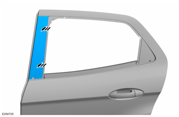
Removal
NOTE: Removal steps in this procedure may contain installation details.
NOTE: LH side shown, RH side similar.
-
Lower the door window glass.
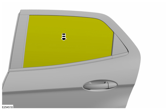 |
Rear door moulding type 1
-
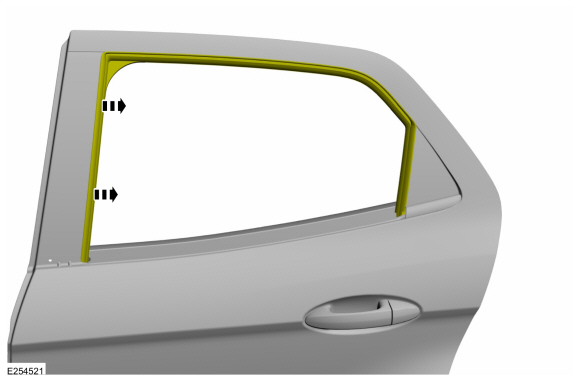
Remove the upper belt moulding screw at front of the door.
 |
-
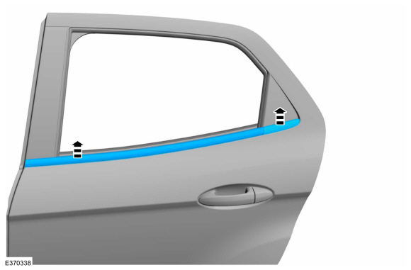
Using a non-marring trim tool, disengage the moulding from the channel in the door and remove the moulding.
 |
-
Position aside the glass run weatherstrip.
 |
-
Remove the rear door moulding, remove and discard the rear door trim cover.
 |
Rear door moulding type 2
-
Remove the rear door trim panel.
Refer to: Rear Door Trim Panel (501-05 Interior Trim and Ornamentation, Removal and Installation).
-
Remove the upper belt moulding screws at the front and rear of the door.
 |
-
Using a non-marring trim tool, disengage the moulding from the channel in the door and remove the moulding.
 |
-
Position aside the glass run weatherstrip.
 |
-
Remove and discard the rear door trim cover.
 |
All vehicles
-
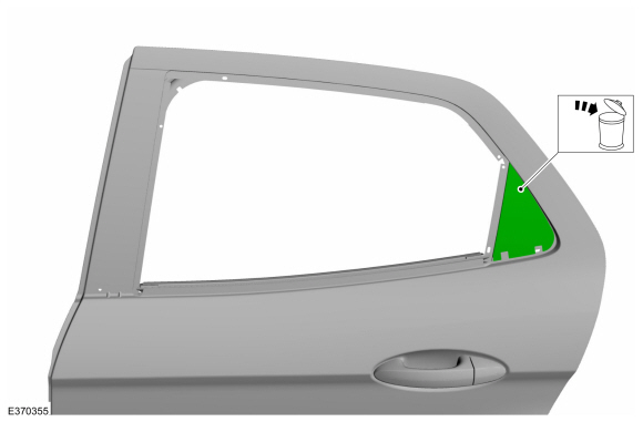
Remove and discard the rear door upper moulding.
 |
Installation
-
NOTE: Make sure that a new component is installed.
Install the rear door upper moulding.
 |
Rear door moulding type 1
-
NOTE: Make sure that a new component is installed.
Install the rear door trim cover and the rear door moulding.
 |
Rear door moulding type 2
-
NOTE: Make sure that a new component is installed.
Install the rear door trim cover.
 |
All vehicles
-
To install, reverse the removal procedure.
 Removal and Installation - Rear Door Moulding
Removal
NOTE:
Removal steps in this procedure may contain installation details.
NOTE:
LH side shown, RH side similar.
NOTICE:
Only use moderate force...
 Removal and Installation - Rear Fender Splash Shield
Removal
NOTE:
Removal steps in this procedure may contain installation details.
NOTE:
LH side shown, RH side similar.
Disengage the pushpin and the clips, position aside the rocker panel moulding...
Other information:
Ford Ecosport 2014-2026 Service and Repair Manual: Description and Operation - Main Control Valve Body
Item Description 1 Transmission internal wiring harness frame 2 Main control valve body 3 Check balls (3 required) 4 Solenoid damper SSA 5 Solenoid body-to-valve body separator plate 6 ..
Ford Ecosport 2014-2026 Service and Repair Manual: Description and Operation - Wipers and Washers - Overview
Overview The windshield wiper/washer system is activated by the wiper/washer switch. The wiper/washer switch is mounted to the right side of the SCCM. The following functions/ features of the windshield wiper/washer system are: Mist wipe Windshield wash Windshield wipers (low/high speed) Intermittent wipers Speed dependent wipers Wiper activa..
Categories
- Manuals Home
- 2nd Gen Ford Ecosport Service Manual (2014 - 2026)
- Removal and Installation - Rear Bumper
- Engine
- Body and Paint
- Removal and Installation - Starter Motor
- Diagnosis and Testing - Evaporative Emissions
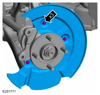
Removal and Installation - Brake Disc Shield
Removal
NOTE: Removal steps in this procedure may contain installation details.
Remove the brake disc.Refer to: Brake Disc (206-03 Front Disc Brake, Removal and Installation).
Remove the bolts and brake disc.
Torque: 80 lb.in (9 Nm)
Copyright © 2026 www.foecosport2.com