Ford Ecosport: Body Closures / Removal and Installation - Liftgate
Ford Ecosport 2014-2026 Service and Repair Manual / Body and Paint / Body Closures / Removal and Installation - Liftgate
Removal
NOTE: Removal steps in this procedure may contain installation details.
-
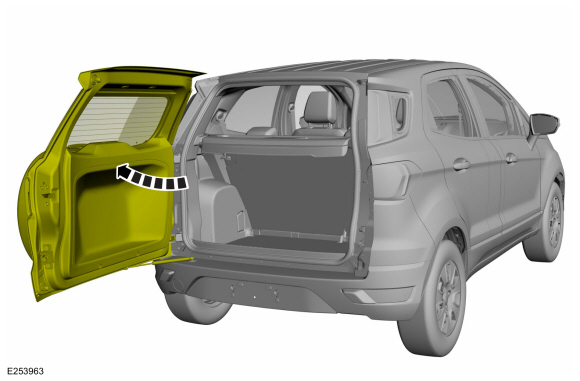
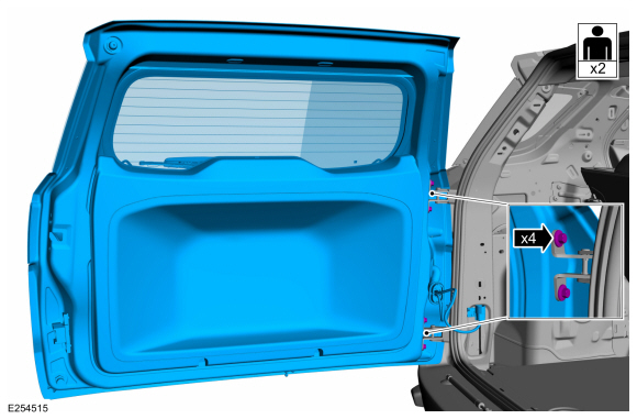
Open the liftgate.
 |
-
Remove the LH loadspace trim panel.
Refer to: Loadspace Trim Panel (501-05 Interior Trim and Ornamentation, Removal and Installation).
-
-
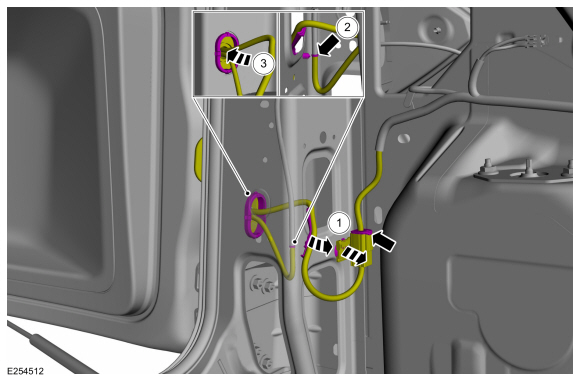
Disconnect the electrical connector and detach the wire harness retainers.
-
Disconnect the rear washer hose.
-
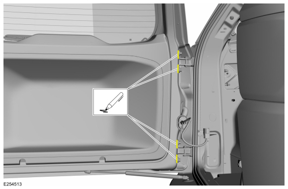
Route the liftgate wiring harness through the body.
-
Disconnect the electrical connector and detach the wire harness retainers.
 |
-
Mark the location of the liftgate hinge bolts.
 |
-
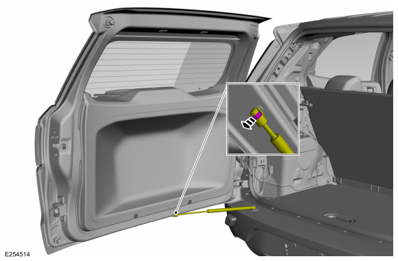
Remove the clip holding the liftgate strut and position aside.
 |
-
NOTE: This step requires the aid of another technician.
Remove the bolts and the liftgate.
Torque: 30 lb.ft (40 Nm)
 |
Installation
-
To install, reverse the removal procedure.
-
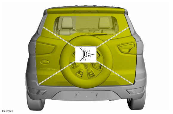
Inspect the body-to-liftgate door dimensions. Align the liftgate as necessary.
Refer to: Liftgate Alignment (501-03 Body Closures, General Procedures).
 |
 Removal and Installation - Hood Hinge
Removal
NOTE:
Removal steps in this procedure may contain installation details.
NOTE:
LH side shown, RH side similar.
Remove the hood...
 Removal and Installation - Liftgate Strut
Removal
Open the liftgate.
Remove the liftgate strut.
Installation
To install, reverse the removal procedure...
Other information:
Ford Ecosport 2014-2026 Service and Repair Manual: Removal and Installation - Front Brake Flexible Hose
Removal Remove the wheel and tire. Refer to: Wheel and Tire (204-04A Wheels and Tires, Removal and Installation). Remove the brake flexible hose bracket bolt. Disconnect the brake tube fitting and remove the brake hose clip...
Ford Ecosport 2014-2026 Service and Repair Manual: Removal and Installation - Front Seat Track Motor Cable
Removal NOTE: Seat removed for clarity. Position the front seat in the full rearward position. Position the front seat in the full upward position. Using a suitable hex wrench locate the access hole and release the tab and position the front seat track motor upward...
Categories
- Manuals Home
- 2nd Gen Ford Ecosport Service Manual (2014 - 2026)
- Removal and Installation - Evaporative Emission Canister Purge Valve
- Service Information
- Diagnosis and Testing - Body Control Module (BCM)
- Removal and Installation - Front Seat
- Engine
Removal and Installation - Oil Pressure Switch
Materials
Name Specification Motorcraft® Thread Sealant with PTFETA-24-B WSK-M2G350-A2
Removal
NOTE: Removal steps in this procedure may contain installation details.
With the vehicle in NEUTRAL, position it on a hoist.Refer to: Jacking and Lifting - Overview (100-02 Jacking and Lifting, Description and Operation).
If equipped, remove the bolts and the underbody shield.
Copyright © 2026 www.foecosport2.com