Ford Ecosport: Information and Entertainment System - General Information / Removal and Installation - FM2 Diversity Antenna Amplifier
Removal
NOTE: Removal steps in this procedure may contain installation details.
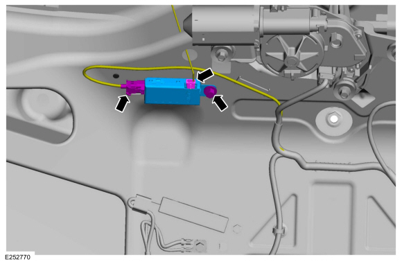
FM2 diversity antenna amplifier
-
Remove the liftgate trim panel.
Refer to: Liftgate Trim Panel (501-05 Interior Trim and Ornamentation, Removal and Installation).
-
Disconnect the connectors, remove the bolt and the FM2 diversity antenna amplifier.
 |
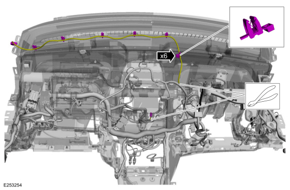
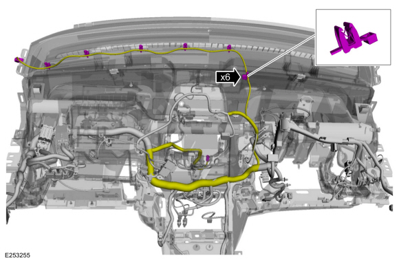
FM2 diversity antenna amplifier instrument panel cable
NOTE: The FM2 diversity antenna amplifier instrument panel cable is part of the instrument panel wiring harness, overlay the replacement cable over the harness and secure it to the instrument panel harness.
-
Remove the instrument panel.
Refer to: Instrument Panel (501-12 Instrument Panel and Console, Removal and Installation).
-
Separate the wire guides and cut the connectors off from the FM2 diversity antenna amplifier cable.
 |
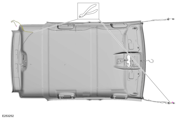
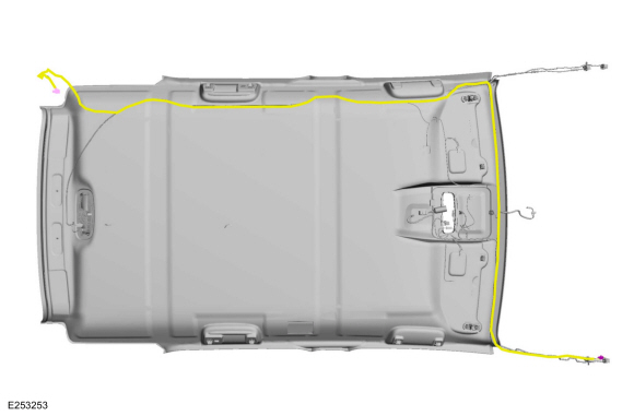
FM2 diversity antenna amplifier headliner cable
NOTE: The FM2 diversity antenna amplifier headliner cable is part of the headliner wiring harness, overlay the replacement cable over the harness and secure it to the headliner harness.
-
Remove the headliner.
Refer to: Headliner (501-05 Interior Trim and Ornamentation, Removal and Installation).
-
Cut the connectors off from the FM2 diversity antenna amplifier cable.
 |
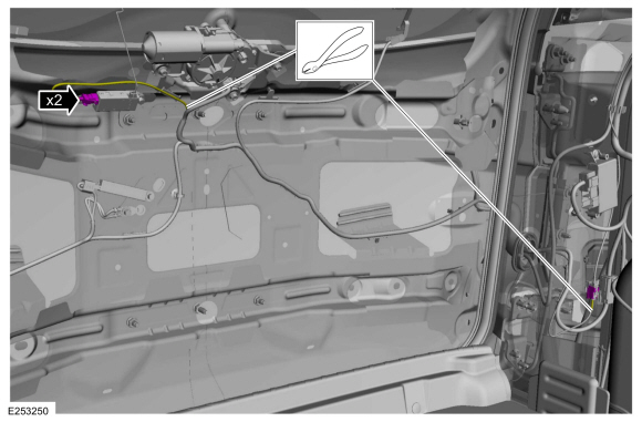
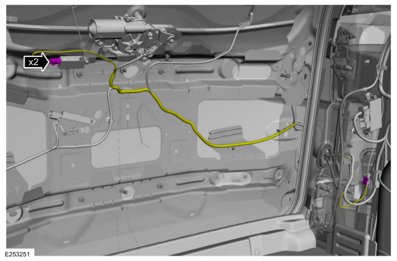
FM2 diversity antenna amplifier liftgate cable
NOTE: The FM2 diversity antenna amplifier liftgate cable is part of the liftgate wiring harness, overlay the replacement cable over the harness and secure it to the liftgate harness.
-
Remove the trim panels for access to the FM2 diversity amplifier liftgate cable.
-
Remove the LH loadspace trim panel.
Refer to: Loadspace Trim Panel (501-05 Interior Trim and Ornamentation, Removal and Installation).
-
Remove the liftgate trim panel.
Refer to: Liftgate Trim Panel (501-05 Interior Trim and Ornamentation, Removal and Installation).
-
Remove the LH loadspace trim panel.
-
Cut the connectors off from the FM2 diversity antenna amplifier cable.
 |
Installation
FM2 diversity antenna amplifier
-
Position the FM2 diversity antenna amplifier, install the bolt and connect the connectors.
Torque: 93 lb.in (10.5 Nm)
|
-
Install the liftgate trim panel.
Refer to: Liftgate Trim Panel (501-05 Interior Trim and Ornamentation, Removal and Installation).
FM2 diversity antenna amplifier instrument panel cable
NOTE: The FM2 diversity antenna amplifier instrument panel cable is part of the instrument panel wiring harness, overlay the replacement cable over the harness and secure it to the instrument panel harness.
-
Overlay and secure the new cable to the instrument panel wiring harness.
 |
-
Install the instrument panel.
Refer to: Instrument Panel (501-12 Instrument Panel and Console, Removal and Installation).
FM2 diversity antenna amplifier headliner cable
NOTE: The FM2 diversity antenna amplifier headliner cable is part of the headliner wiring harness, overlay the replacement cable over the harness and secure it to the headliner harness.
-
Overlay and secure the new cable to the headliner wiring harness.
 |
-
Install the headliner.
Refer to: Headliner (501-05 Interior Trim and Ornamentation, Removal and Installation).
FM2 diversity antenna amplifier liftgate cable
NOTE: The FM2 diversity antenna amplifier liftgate cable is part of the liftgate wiring harness, overlay the replacement cable over the harness and secure it to the liftgate harness.
-
Overlay and secure the new cable to the liftgate wiring harness and connect the connectors.
 |
-
Install the trim panels removed for access to the FM2 diversity amplifier liftgate cable.
-
Install the LH loadspace trim panel.
Refer to: Loadspace Trim Panel (501-05 Interior Trim and Ornamentation, Removal and Installation).
-
Install the liftgate trim panel.
Refer to: Liftgate Trim Panel (501-05 Interior Trim and Ornamentation, Removal and Installation).
-
Install the LH loadspace trim panel.
 Removal and Installation - Cellular Phone Antenna Cable
Removal
NOTE:
Removal steps in this procedure may contain installation details.
NOTE:
The original equipment cellular phone antenna cable is part
of the wiring harness and cannot be removed...
 Removal and Installation - Front Controls Interface Module (FCIM)
Special Tool(s) /
General Equipment
Interior Trim Remover
Removal
NOTE:
8 inch display is shown, all other displays are similar...
Other information:
Ford Ecosport 2014-2026 Service and Repair Manual: Removal and Installation - Front Halfshaft LH - 6-Speed Automatic Transmission – 6F35
Special Tool(s) / General Equipment 204-161 (T97P-1175-A) Installer, HalfshaftTKIT-1997-LM2TKIT-1997-F/FM2TKIT-1997-FLM2 205-D070 (D93P-1175-B) Remover, Front Wheel Hub 211-001 (TOOL-3290-D) Remover, Tie-Rod End Removal NOTE: Removal steps in this procedure may contain installation details...
Ford Ecosport 2014-2026 Service and Repair Manual: Removal and Installation - Front Seat Track Motor Cable
Removal NOTE: Seat removed for clarity. Position the front seat in the full rearward position. Position the front seat in the full upward position. Using a suitable hex wrench locate the access hole and release the tab and position the front seat track motor upward...
Categories
- Manuals Home
- 2nd Gen Ford Ecosport Service Manual (2014 - 2026)
- Removal and Installation - Fuel Pump and Sender Unit
- Specifications
- Description and Operation - Evaporative Emissions - System Operation and Component Description
- Automatic Transmission - 6-Speed Automatic Transmission – 6F35
- Removal and Installation - Rear Bumper
Removal and Installation - Oil Pressure Switch
Materials
Name Specification Motorcraft® Thread Sealant with PTFETA-24-B WSK-M2G350-A2
Removal
NOTE: Removal steps in this procedure may contain installation details.
With the vehicle in NEUTRAL, position it on a hoist.Refer to: Jacking and Lifting - Overview (100-02 Jacking and Lifting, Description and Operation).
If equipped, remove the bolts and the underbody shield.