Ford Ecosport: Supplemental Restraint System / Removal and Installation - Driver Airbag
Special Tool(s) / General Equipment
| Flat-Bladed Screwdriver |
Removal
 WARNING:
The following procedure prescribes critical repair steps
required for correct restraint system operation during a crash. Follow
all notes and steps carefully. Failure to follow step instructions may
result in incorrect operation of the restraint system and increases the
risk of serious personal injury or death in a crash.
WARNING:
The following procedure prescribes critical repair steps
required for correct restraint system operation during a crash. Follow
all notes and steps carefully. Failure to follow step instructions may
result in incorrect operation of the restraint system and increases the
risk of serious personal injury or death in a crash.
-
Refer to: Pyrotechnic Device Health and Safety Precautions (100-00 General Information, Description and Operation).
WARNING:
Before beginning any service procedure in this
manual, refer to health and safety warnings in section 100-00 General
Information. Failure to follow this instruction may result in serious
personal injury.
-
Depower the SRS .
Refer to: Supplemental Restraint System (SRS) Depowering (501-20B Supplemental Restraint System, General Procedures).
-
Remove the steering column shrouds.
Refer to: Steering Column Shrouds (501-05 Interior Trim and Ornamentation, Removal and Installation).
-
-
Turn the steering wheel clockwise through 90 degrees.
-
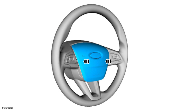
Pivot the spring clip to disengage it from the driver airbag.
Use the General Equipment: Flat-Bladed Screwdriver
-
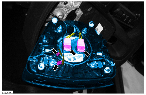
Detach the driver airbag.
-
Turn the steering wheel clockwise through 90 degrees.
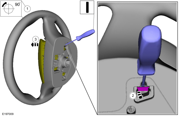 |
-
-
Turn the steering wheel counter-clockwise through 180 degrees.
-
Pivot the spring clip to disengage it from the driver airbag.
Use the General Equipment: Flat-Bladed Screwdriver
-
Detach the driver airbag.
-
Turn the steering wheel counter-clockwise through 180 degrees.
 |
-
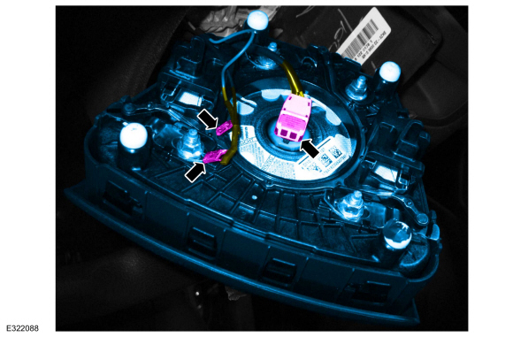
For a single stage driver airbag.
Disconnect the electrical connectors and remove the driver airbag.
 |
-
For a dual stage driver airbag.
Disconnect the electrical connectors and remove the driver airbag.
 |
Installation
WARNING:
Incorrect repair techniques or actions can cause an
accidental pyrotechnic device deployment. Make sure the supplemental
restraint and pedestrian protection system (if equipped) is depowered
before reconnecting the component. Refer to the depowering General
Procedure in section 501-20B. Failure to precisely follow depowering
instructions could result in serious personal injury from an accidental
deployment.
-
To install, reverse the removal procedure.
-
NOTE: An audible click is heard when each side of the driver airbag is pushed in and the spring clip seats behind the steering wheel retainer.
Align the driver airbag to the steering wheel and push in on each side at the same time, to engage the driver airbag spring clip to the steering wheel retainers.
-
After installation, pull the driver airbag from the 3
and 9 o'clock positions to make sure it is retained in the steering
wheel.
-
After installation, pull the driver airbag from the 3
and 9 o'clock positions to make sure it is retained in the steering
wheel.
 |
-
Repower the SRS .
Refer to: Supplemental Restraint System (SRS) Repowering (501-20B Supplemental Restraint System, General Procedures).
 Removal and Installation - Clockspring
Removal
WARNING:
The following procedure prescribes critical repair steps
required for correct restraint system operation during a crash...
 Removal and Installation - Driver Knee Airbag
Special Tool(s) /
General Equipment
Pick Hook
Interior Trim Remover
Removal
WARNING:
The following procedure prescribes critical repair steps
required for correct restraint system operation during a crash...
Other information:
Ford Ecosport 2014-2026 Service and Repair Manual: General Procedures - Ride Height Measurement
Special Tool(s) / General Equipment Surface Gauge Check Ride Height Measurement - Front NOTE: Make sure that the vehicle is positioned on a flat, level surface and the tires are inflated to the correct pressure. Vehicle should have a full tank of fuel...
Ford Ecosport 2014-2026 Service and Repair Manual: Diagnosis and Testing - Pinpoint Test - DTC: AP, Vehicles With: Rear Seat Side Airbag
U0151:00 Normal Operation and Fault Conditions The OCSM uses information contained in messages from the RCM sent on the HS-CAN2 . DTC Fault Trigger Conditions DTC Description Fault Trigger Conditions U0151:00 Lost Communication with Restraints Control Module: No..
Categories
- Manuals Home
- 2nd Gen Ford Ecosport Service Manual (2014 - 2026)
- General Procedures - Transmission Fluid Level Check
- Removal and Installation - Rear Bumper
- General Procedures - Battery Charging
- Removal and Installation - Blower Motor
- Description and Operation - Evaporative Emissions - System Operation and Component Description
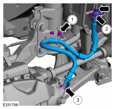
Removal and Installation - Front Brake Flexible Hose
Removal
Remove the wheel and tire.Refer to: Wheel and Tire (204-04A Wheels and Tires, Removal and Installation).
Remove the brake flexible hose bracket bolt.
Disconnect the brake tube fitting and remove the brake hose clip.
Loosen the brake hose fitting and remove the brake flexible hose.