Ford Ecosport: Supplemental Restraint System / Removal and Installation - Driver Knee Airbag
Special Tool(s) / General Equipment
| Pick Hook | |
| Interior Trim Remover |
Removal
 WARNING:
The following procedure prescribes critical repair steps
required for correct restraint system operation during a crash. Follow
all notes and steps carefully. Failure to follow step instructions may
result in incorrect operation of the restraint system and increases the
risk of serious personal injury or death in a crash.
WARNING:
The following procedure prescribes critical repair steps
required for correct restraint system operation during a crash. Follow
all notes and steps carefully. Failure to follow step instructions may
result in incorrect operation of the restraint system and increases the
risk of serious personal injury or death in a crash.
NOTE: Removal steps in this procedure may contain installation details.
-
Refer to: Pyrotechnic Device Health and Safety Precautions (100-00 General Information, Description and Operation).
WARNING:
Before beginning any service procedure in this
manual, refer to health and safety warnings in section 100-00 General
Information. Failure to follow this instruction may result in serious
personal injury.
-
Depower the SRS .
Refer to: Supplemental Restraint System (SRS) Depowering (501-20B Supplemental Restraint System, General Procedures).
-
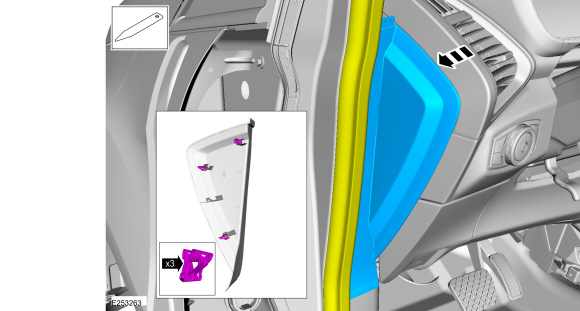
Position aside the weather strip, release the clips and remove the LH instrument panel side trim panel.
 |
-
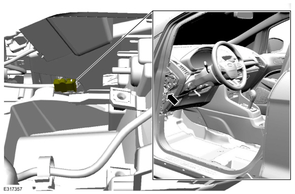
Locate the driver knee airbag electrical connector.
 |
-
-
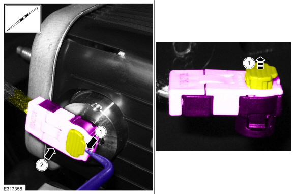
Lift and release the driver knee airbag electrical connector locking wedge.
Use the General Equipment: Pick Hook
-
Disconnect the driver knee airbag electrical connector.
-
Lift and release the driver knee airbag electrical connector locking wedge.
 |
-
Remove the screws and the instrument panel insulator.
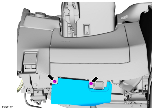 |
-
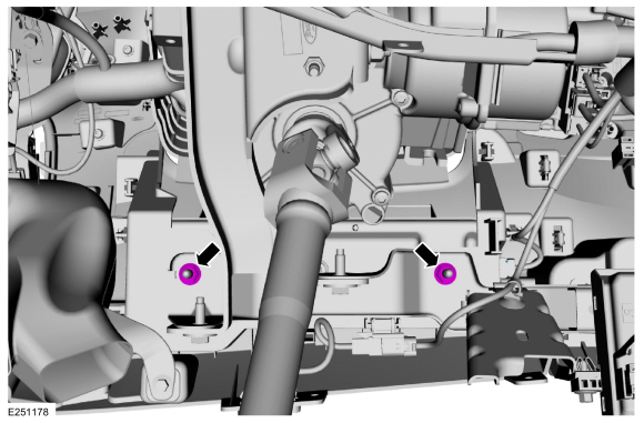
Remove the driver knee airbag nuts.
Torque: 71 lb.in (8 Nm)
 |
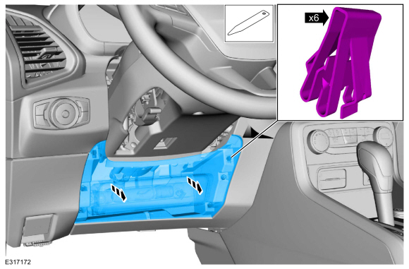
-
Detach the clips and remove the driver knee airbag.
Use the General Equipment: Interior Trim Remover
 |
Installation
WARNING:
Incorrect repair techniques or actions can cause an
accidental Supplemental Restraint System deployment. Make sure the
restraint system is depowered before reconnecting the component. Refer
to the Supplemental Restraint System depowering General Procedure in
section 501-20B. Failure to precisely follow depowering instructions
could result in serious personal injury from an accidental deployment.
-
To install, reverse the removal procedure.
-
Repower the SRS .
Refer to: Supplemental Restraint System (SRS) Repowering (501-20B Supplemental Restraint System, General Procedures).
 Removal and Installation - Driver Airbag
Special Tool(s) /
General Equipment
Flat-Bladed Screwdriver
Removal
WARNING:
The following procedure prescribes critical repair steps
required for correct restraint system operation during a crash...
 Removal and Installation - Front Door Side Impact Sensor - Vehicles With: Rear Seat Side Airbag
Removal
WARNING:
The following procedure prescribes critical repair steps
required for correct restraint system operation during a crash...
Other information:
Ford Ecosport 2014-2026 Service and Repair Manual: General Procedures - Locked Seatbelt Retractor Releasing
Repair NOTE: If the seatbelt webbing does not extract from the seatbelt retractor from the stowed position, this may be due to a normal condition which happens when the seatbelt retracts at a high rate of speed. Follow these steps to release the seatbelt...
Ford Ecosport 2014-2026 Service and Repair Manual: Removal and Installation - Body Control Module (BCM)
Removal NOTE: Removal steps in this procedure may contain installation details. NOTE: If installing a new module, it is necessary to upload the module configuration information to the diagnostic scan tool prior to removing the module...
Categories
- Manuals Home
- 2nd Gen Ford Ecosport Service Manual (2014 - 2026)
- Diagnosis and Testing - Evaporative Emissions
- Removal and Installation - Roof Rail
- Specifications
- Diagnosis and Testing - Body Control Module (BCM)
- Description and Operation - Jacking and Lifting - Overview
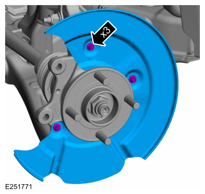
Removal and Installation - Brake Disc Shield
Removal
NOTE: Removal steps in this procedure may contain installation details.
Remove the brake disc.Refer to: Brake Disc (206-03 Front Disc Brake, Removal and Installation).
Remove the bolts and brake disc.
Torque: 80 lb.in (9 Nm)