Ford Ecosport: Battery, Mounting and Cables / Removal and Installation - Battery Tray
Removal
NOTE: Removal steps in this procedure may contain installation details.
-
Remove the battery.
Refer to: Battery (414-01 Battery, Mounting and Cables, Removal and Installation).
1.0L EcoBoost (92kW/125PS) (B7)
-
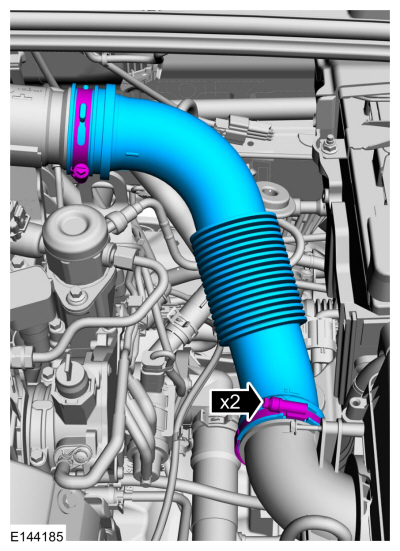
NOTICE: The turbocharger compressor vanes can be damaged by even the smallest particles. When removing any turbocharger or engine air intake system component, ensure that no debris enters the system. Failure to do so may result in damage to the turbocharger.
Remove the air cleaner outlet tube.
Torque: 44 lb.in (5 Nm)
 |
All vehicles
-
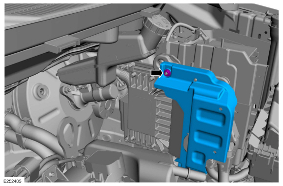
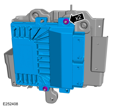
Remove the nut and the PCM cover.
Torque: 44 lb.in (5 Nm)
 |
-
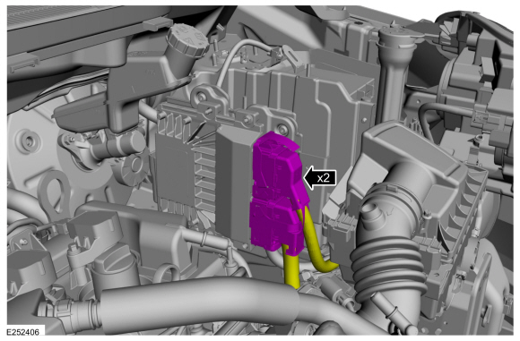
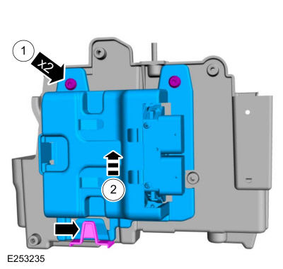
NOTE: Gas vehicle with 2 PCM electrical connectors shown, diesel vehicles have a PCM with 3 electrical connectors.
Disconnect the PCM electrical connectors.
 |
-
-
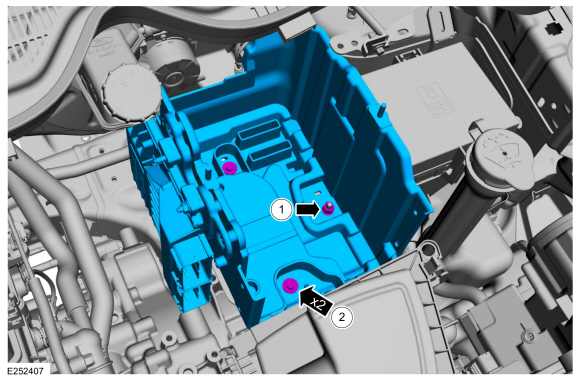
Remove the battery tray nut.
Torque: 55 lb.in (6.2 Nm)
-
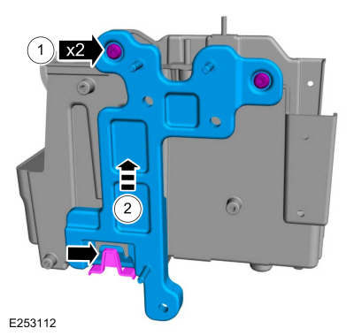
Remove the bolts and the battery tray.
Torque: 55 lb.in (6.2 Nm)
-
Remove the battery tray nut.
 |
1.5L
NOTE: The following steps are only necessary when installing a new component.
-
-
Remove the PCM screws.
-
Lifting upward, remove the PCM from the battery tray.
-
Remove the PCM screws.
 |
1.5L
-
NOTE: The following steps are only necessary when installing a new component.
Remove the nuts and the PCM .
Torque: 44 lb.in (5 Nm)
 |
-
-
Remove the PCM mounting bracket screws.
-
Lifting upward, remove the PCM mounting bracket from the battery tray.
-
Remove the PCM mounting bracket screws.
 |
All vehicles
-
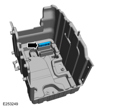
If equipped, remove the battery spacer.
 |
Installation
-
To install, reverse the removal procedure.
-
NOTICE: If necessary, install a spacer inside the battery tray in the correct position to prevent battery movement.
NOTE: The following step is only necessary when installing a new component.
If necessary, install a battery spacer.
|
 Removal and Installation - Battery Monitoring Sensor
Removal
NOTE:
When the battery is disconnected and connected, some
abnormal drive symptoms may occur while the vehicle relearns its
adaptive strategy...

Other information:
Ford Ecosport 2014-2026 Service and Repair Manual: Diagnosis and Testing - Powertrain Control Module (PCM) Input and Output Controls
Diagnostic Trouble Code (DTC) Chart Diagnostics in this manual assume a certain skill level and knowledge of Ford-specific diagnostic practices. REFER to: Diagnostic Methods (100-00 General Information, Description and Operation). Module DTC Description Action PCM P0219:00 Engine Overspeed Condition: No Sub Type Information GO to Pinpoint Test Z PCM P0297..
Ford Ecosport 2014-2026 Service and Repair Manual: Removal and Installation - Rear Stabilizer Bar Link
Removal NOTICE: Suspension fasteners are critical parts that affect the performance of vital components and systems. Failure of these fasteners may result in major service expense. Use the same or equivalent parts if replacement is necessary. Do not use a replacement part of lesser quality or substitute design. Tighten fasteners as specified. NOTE: Removal steps in this proc..
Categories
- Manuals Home
- 2nd Gen Ford Ecosport Service Manual (2014 - 2026)
- Description and Operation - Evaporative Emissions - System Operation and Component Description
- Removal and Installation - Roof Rail
- Removal and Installation - Fuel Pump and Sender Unit
- Removal and Installation - Evaporative Emission Canister Purge Valve
- Body and Paint
Removal and Installation - Front Stabilizer Bar
Special Tool(s) / General Equipment
Tie Rod End Remover Transmission JackRemoval
NOTICE: Suspension fasteners are critical parts that affect the performance of vital components and systems. Failure of these fasteners may result in major service expense. Use the same or equivalent parts if replacement is necessary. Do not use a replacement part of lesser quality or substitute design. Tighten fasteners as specified.
NOTE: Removal steps in this procedure may contain installation details.
NOTICE: Disconnect the b