Ford Ecosport: Battery, Mounting and Cables / Removal and Installation - Battery Monitoring Sensor
Ford Ecosport 2014-2026 Service and Repair Manual / Battery and Charging System / Battery, Mounting and Cables / Removal and Installation - Battery Monitoring Sensor
Removal
NOTE: When the battery is disconnected and connected, some abnormal drive symptoms may occur while the vehicle relearns its adaptive strategy. The vehicle may need to be driven to allow the PCM to relearn the adaptive strategy values.
NOTE: The battery monitoring sensor and cable are serviced as an assembly.
NOTE: Removal steps in this procedure may contain installation details.
-
-
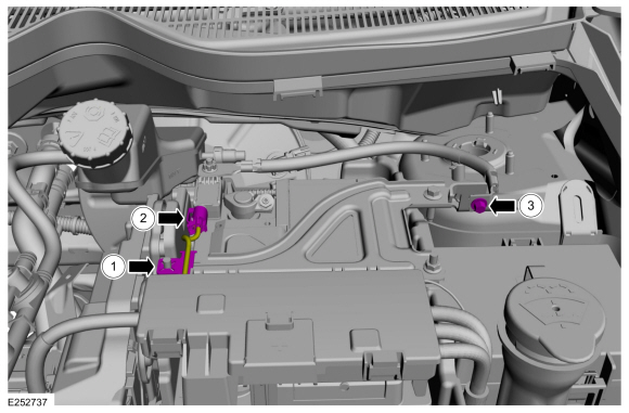
Detach the wire harness retainer from the battery tray hold-down bracket.
-
Disconnect the battery monitoring sensor electrical connector.
-
Remove the negative battery cable ground bolt from the LH strut tower bracket.
Torque: 106 lb.in (12 Nm)
-
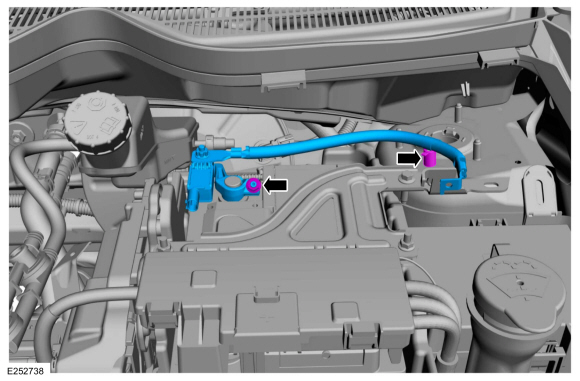
Detach the wire harness retainer from the battery tray hold-down bracket.
 |
-
Loosen the nut, detach the negative battery cable retainer and remove the battery monitoring sensor assembly.
Torque: 44 lb.in (5 Nm)
 |
Installation
-
To install, reverse the removal procedure.
 Removal and Installation - Battery Cables - 2.0L Duratec-HE (125kW/170PS) – MI4
Removal
NOTE:
The starter and generator electrical connector and
terminals are integrated into the engine wiring harness and the battery
positive terminal is integrated into the Battery Junction Box (BJB)...
 Removal and Installation - Battery Tray
Removal
NOTE:
Removal steps in this procedure may contain installation details.
Remove the battery.
Refer to: Battery (414-01 Battery, Mounting and Cables, Removal and Installation)...
Other information:
Ford Ecosport 2014-2026 Service and Repair Manual: Removal and Installation - Selector Lever Bezel
Special Tool(s) / General Equipment Interior Trim Remover Removal All vehicles Remove the selector lever knob. Refer to: Selector Lever Knob (307-05 Automatic Transmission External Controls, Removal and Installation)...
Ford Ecosport 2014-2026 Service and Repair Manual: General Procedures - Speaker Audio Test
Activation NOTE: The procedure used to download the audio files varies, depending on the web browser used. Using a suitable web browser, download all of the diagnostic sound tracks to a suitable USB drive. 125Hz Sample 100Hz Sample 80Hz Sample 63Hz Sample 50Hz Sample 4..
Categories
- Manuals Home
- 2nd Gen Ford Ecosport Service Manual (2014 - 2026)
- General Procedures - Battery Charging
- Removal and Installation - Blower Motor
- Description and Operation - Jacking and Lifting - Overview
- Specifications
- Removal and Installation - Body Control Module (BCM)
Removal and Installation - Oil Pressure Switch
Materials
Name Specification Motorcraft® Thread Sealant with PTFETA-24-B WSK-M2G350-A2
Removal
NOTE: Removal steps in this procedure may contain installation details.
With the vehicle in NEUTRAL, position it on a hoist.Refer to: Jacking and Lifting - Overview (100-02 Jacking and Lifting, Description and Operation).
If equipped, remove the bolts and the underbody shield.
Copyright © 2026 www.foecosport2.com