Ford Ecosport: Automatic Transmission - 6-Speed Automatic Transmission – 6F35 / Overhaul - Main Control Valve Body
Special Tool(s) /
General Equipment
 |
307-636
Alignment Pins- Valve Body
TKIT-2008ET-FLM
TKIT-2008ET-ROW |
| Flat Headed Screw Driver |
| Magnetic Socket |
| Long Nose Pliers |
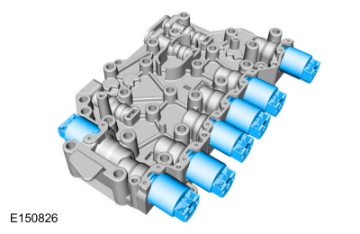
Main Control Valve Body and Solenoid Body
-
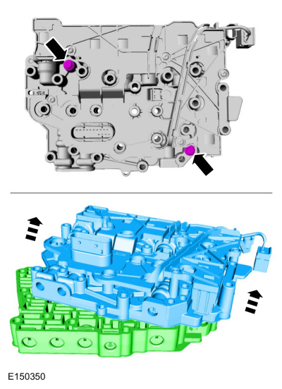
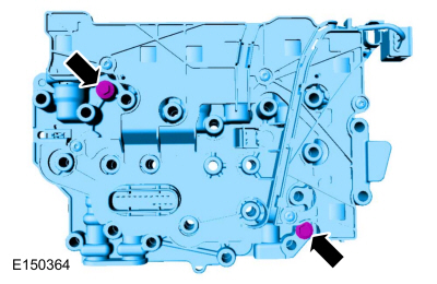
Remove the solenoid body-to-valve body bolts and separate the solenoid body from the valve body.
-
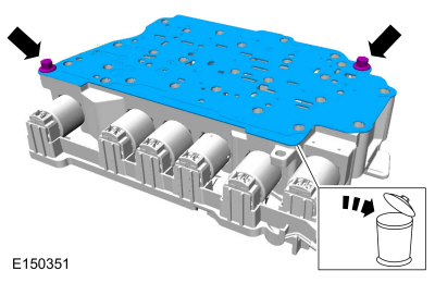
Remove the separator plate-to-solenoid body bolts and remove and discard the separator plate.
Main Control Valve Body
-
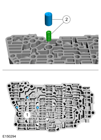
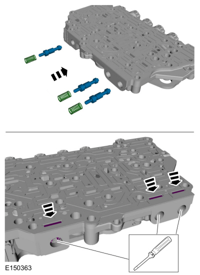
Remove the check balls, solenoid damper and the spring.
-
Check balls
-
Solenoid damper and spring
-
Remove the manual valve.
 |
|
-
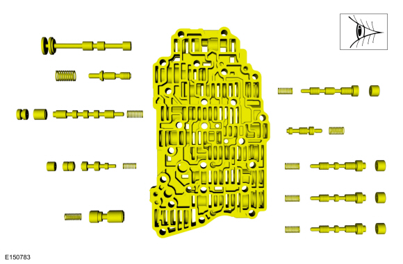
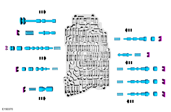
NOTICE:
Remove the valves by tapping the valve body on the
palm of the hand to slide the valves out of the bores or by threading a
4-mm bolt into the valves and pulling them out. If it is necessary to
use a pick, use extreme caution to prevent damaging the valves or valve
bores. If necessary, disassemble parts of the main control valve body in
small groups. Arrange the parts as they are removed to avoid mixing
similar pieces.
NOTE:
The bypass valve is held in with a spring-loaded
retainer. Be careful not to lose the retainer when removing it.
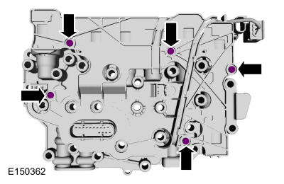
Compress the valve springs with a screwdriver and remove
the retainers with a magnet. Use a pick to remove the bypass valve
retainer. Remove the individual valves and springs from the main control
valve body by tapping the valve body on the palm of the hand to slide
the valves out of the bores. If needed, use a 4-mm bolt to thread into
the valves to remove the valves.
Use the General Equipment: Flat Headed Screw Driver
Use the General Equipment: Magnetic Socket
 |
|
-
NOTICE:
Do not stone or polish any valves or damage to the
valves can occur. If the valves do not move freely, install a new
assembly.
Clean the valves, springs and main control valve body.
-
NOTICE:
Do not stone or polish any valves or damage to the
valves can occur. If the valves do not move freely, install a new
assembly.
Install the valve body valves, springs and retaining
clips in the main control valve body. For valve and spring locations
Refer to: Main Control Valve Body (307-01B Automatic Transmission -
6-Speed Automatic Transmission – 6F35, Description and Operation).
-
Install the manual valve in the valve body.
-
Install the check balls, spring and the solenoid damper.
-
Check balls
-
Solenoid damper and spring
Solenoid Body
-
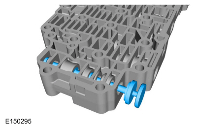
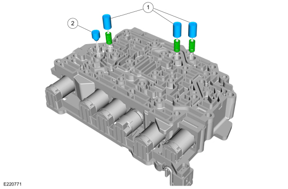
Remove the solenoid body dampers and springs.
-
Damper pistons and springs
-
Elastomeric damper
-
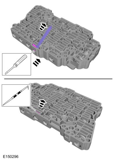
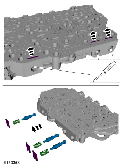
Compress the valve springs and remove the retainers with
a magnet. Remove the individual valves and springs from the solenoid
body by tapping it on the palm of the hand to slide the valves out of
the bores.
Use the General Equipment: Flat Headed Screw Driver
Use the General Equipment: Magnetic Socket
-
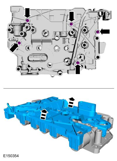
NOTICE:
Be careful not to bend or twist the transmission
internal wiring harness frame or solenoid terminals when removing the
transmission internal wiring harness frame or damage can occur.
Remove the screws and carefully remove the transmission
internal wiring harness frame from the solenoids by lifting it straight
up evenly.
-
NOTICE:
The solenoids are calibrated from the factory and
are not all the same. Failure to mark the solenoids to the ports they
were originally in can result in mixing the solenoids and cause damage
to the transmission or a harsh shift.
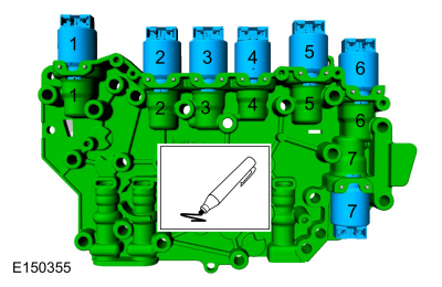
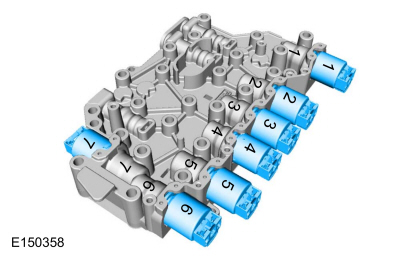
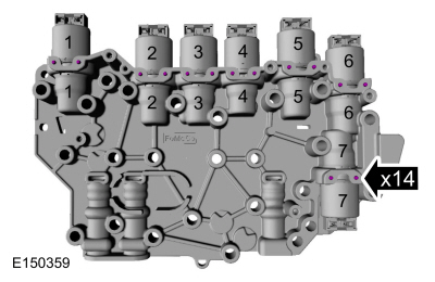
Using a paint marker, number the solenoids and the
solenoid body to correspond with the ports from which the solenoids are
located in the solenoid body
-
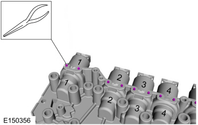
Remove the solenoid retaining pins.
Use the General Equipment: Long Nose Pliers
-
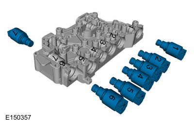
Remove the solenoids from the solenoid body.
-
NOTICE:
Be careful not to wash the numbers from the
solenoids or the solenoid body. Failure to install the solenoids in the
ports they were originally in can result in damage to the transmission
or a harsh shift.
NOTICE:
Do not stone or polish any valves or damage to the
valves can occur. If the valves do not move freely during assembly,
install a new solenoid body.
Clean and inspect the solenoid body, solenoids and valve assemblies for damage.
-
Inspect the solenoid screens for debris that may restrict fluid flow through the screen.
-
NOTICE:
The solenoids are calibrated from the factory and
are not all the same. Failure to install the solenoids in the ports they
were originally in can result in damage to the transmission or a harsh
shift.
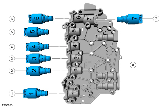
If new solenoid(s) are not being installed, position the solenoids in their corresponding solenoid body ports.
-
NOTE:
If installing a new Variable Force Solenoid (VFS), determine the base
part number of the solenoid(s). The TCC solenoid, SSA and SSC are all
normally low pressure solenoids. The LPC solenoid, SSB and SSD are all
normally high pressure solenoids. SSE is not a Variable Force Solenoid
(VFS); it is an ON/OFF solenoid.
-
LPC solenoid (normally high) part number 7G383
-
SSC (normally low) part number 7G136
-
TCC solenoid (normally low) part number 7G136
-
SSE (normally closed [OFF]) part number 7G484
-
SSA (normally low) part number 7G136
-
SSB (normally high) part number 7G383
-
SSD (normally high) part number 7G383
-
Solenoid body part number 7G391
 |
|
-
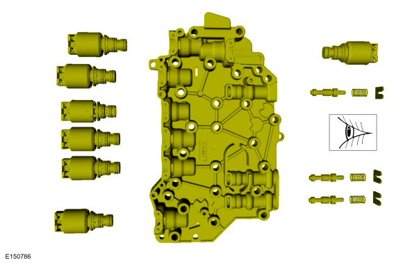
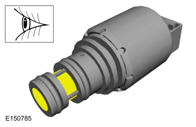
If installing new solenoids, note the color of the
plastic nozzle and the large O-ring. High pressure solenoids, such as
the LPC solenoid, SSB and SSD , have black plastic nozzles and orange
O-rings. Low pressure solenoids, such as the TCC solenoid, SSA and SSC ,
have brown plastic nozzles and green O-rings. The solenoids can only be
replaced with the same color solenoid.
-
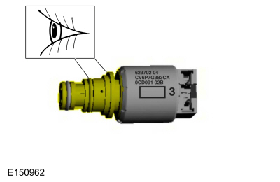
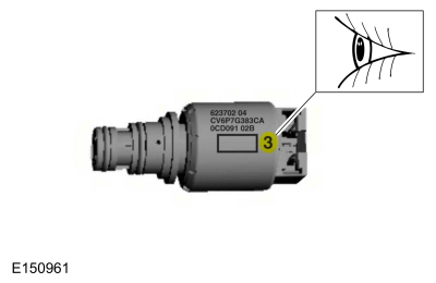
Determine the part number suffix by checking the
solenoid service band number etched on the side of the solenoid. The
band number is next to the two-dimensional matrix barcode on the side of
the solenoid and will be a 1, 2, 3, 4 or 5. Determine the part number
suffix and match the new solenoid base part number and suffix with the
old solenoid.
-
= (B)
-
= (C)
-
= (D)
-
= (E)
-
= (F)
-
Install the solenoid(s) in the solenoid body.
-
Install the solenoid retaining pin(s).
-
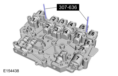
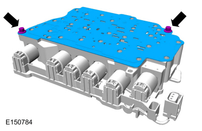
Install the special tools in the solenoid body to align
the transmission internal wiring harness frame for installation.
Use Special Service Tool: 307-636
Alignment Pins- Valve Body.
-
NOTICE:
Be careful not to bend or twist the transmission
internal wiring harness frame or solenoid terminals when removing the
transmission internal wiring harness frame or damage can occur.
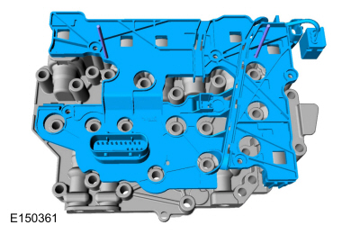
Position the transmission internal wiring harness frame
on the guide pins and carefully install the transmission internal wiring
harness frame by pushing it straight down into the solenoids.
-
Install the transmission internal wiring harness frame screws.
Torque:
31 lb.in (3.5 Nm)
-
NOTICE:
If the valves do not move freely during assembly,
install a new solenoid body. Failure to install a new solenoid body can
result in a harsh shift or damage to the transmission.
Install the solenoid body valves, springs and retaining
clips in the solenoid body. For valve and spring locations
Refer to: Main Control Valve Body (307-01B Automatic Transmission -
6-Speed Automatic Transmission – 6F35, Description and Operation).
Use the General Equipment: Flat Headed Screw Driver
-
Install the solenoid body dampers and springs.
-
Damper pistons and springs
-
Elastomeric damper
Main Control Valve Body and Solenoid Body
-
Install the new separator plate and the separator plate-to-solenoid body bolts.
Torque:
89 lb.in (10 Nm)
-
Position the solenoid body assembly on the valve body and install the solenoid body-to-valve body bolts.
Torque:
89 lb.in (10 Nm)
Removal
With the vehicle in NEUTRAL, position it on a hoist.
Refer to: Jacking and Lifting - Overview (100-02 Jacking and Lifting, Description and Operation)...
Special Tool(s) /
General Equipment
100-001
(T50T-100-A)
Slide Hammer
100-002
(TOOL-4201-C)
Holding Fixture with Dial Indicator Gauge
205-153
(T80T-4000-W)
Handle
205-990Installer, Axle SealTKIT-2012A-FLTKIT-2012A-ROW
211-061
(T78P-3504-N1)
Remover, Roll Pin
303-D011
(D80L-100-G)
Actuator Pin (Dia 3/16)
..
Other information:
DTC Chart: Restraint Control Module (RCM)
Diagnostics in this manual assume a certain skill level and knowledge of Ford-specific diagnostic practices. REFER to: Diagnostic Methods (100-00 General Information, Description and Operation).
NOTE:
Unlisted Diagnostic Trouble Codes (DTCs) are often retrieved
as a result of incorrect repair procedures. Before attempting any
repairs for unli..
DTC Chart: Body Control Module (BCM)
Diagnostics in this manual assume a certain skill level and knowledge of Ford-specific diagnostic practices. REFER to: Diagnostic Methods (100-00 General Information, Description and Operation).
BCM
DTC Chart
DTC
Description
Action
B1026:04
Steering Col..
 Removal and Installation - Turbine Shaft Speed (TSS) Sensor
 Overhaul - Transmission