Ford Ecosport: Suspension System - General Information / General Procedures - Ride Height Measurement
Ford Ecosport 2014-2026 Service and Repair Manual / Suspension / Suspension System - General Information / General Procedures - Ride Height Measurement
Special Tool(s) / General Equipment
| Surface Gauge |
Check
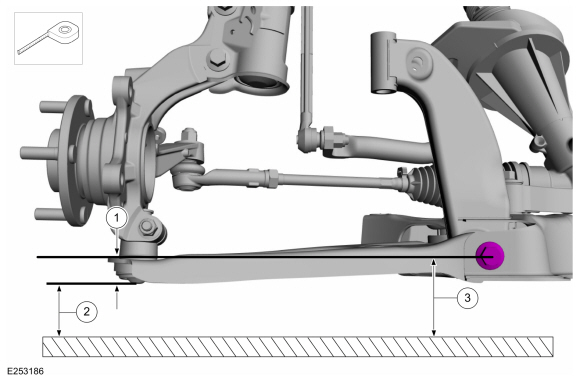
Ride Height Measurement - Front
NOTE: Make sure that the vehicle is positioned on a flat, level surface and the tires are inflated to the correct pressure. Vehicle should have a full tank of fuel.
-
-
Ride height = 3-2
-
Measure the distance between the flat level
surface and the end cap of the lower arm ball joint (measurement 2)
-
Measure the distance between the flat level
surface and the center of the lower arm forward bolt (measurement 3)
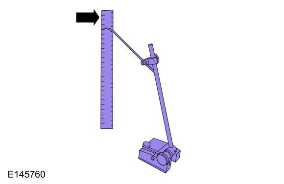
Use the General Equipment: Surface Gauge
-
Ride height = 3-2
 |
-
With the surface gauge positioned on a flat, level
surface, record the measurement of the surface gauge position
(measurement 2) and (measurement 3).
Use the General Equipment: Surface Gauge
 |
-
Subtract measurement 2 from measurement 3 to obtain the front ride height.
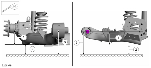
Rear Ride Height Measurement - FWD
NOTE: Make sure that the vehicle is positioned on a flat, level surface and the tires are inflated to the correct pressure. Vehicle should have a full tank of fuel.
-
-
Ride height = 3-2
-
Measurement 2
-
Measurement 3
Use the General Equipment: Surface Gauge
-
Ride height = 3-2
 |
-
Measure the distance between the flat level surface
and the center of the rear beam axle bushing bolt (inner part)
(measurement 3).
-
Measure the distance between the flat level surface and the side arm profile lower edge (measurement 2).
-
Subtract measurement 2 from measurement 3 to obtain the rear ride height.
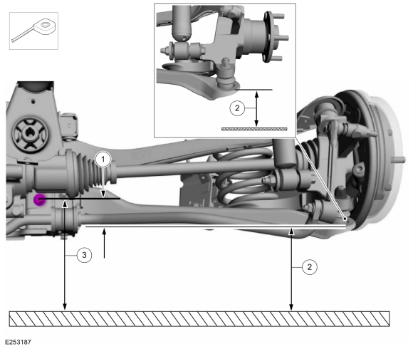
Rear Ride Height Measurement - AWD
NOTE: Make sure that the vehicle is positioned on a flat, level surface and the tires are inflated to the correct pressure. Vehicle should have a full tank of fuel.
-
-
Ride height = 3-2
-
Measurement 2
-
Measurement 3
Use the General Equipment: Surface Gauge
-
Ride height = 3-2
 |
-
Measure the distance between the flat level surface
and the center of the rearward lower arm-to-frame bolt (measurement 3).
-
Measure the distance between the flat level surface
and the end cap of the rear lower arm ball joint (measurement 2).
-
Subtract measurement 2 from measurement 3 to obtain the rear ride height.
 General Procedures - Rear Toe Adjustment - AWD
Special Tool(s) /
General Equipment
Wheel Alignment System
Adjustment
NOTICE:
Do not use any tools or equipment to move the wheel and tire
assembly or suspension components while checking for relative movement...

Other information:
Ford Ecosport 2014-2026 Service and Repair Manual: Diagnosis and Testing - Pinpoint Test - DTC: M, Vehicles With: Rear Seat Side Airbag
B0082:11, B0082:12, B0082:13, B0082:1A Refer to Wiring Diagrams Cell 46 for schematic and connector information. Normal Operation and Fault Conditions The RCM continuously monitors the passenger seatbelt load limiter circuits for the following faults: Resistance out of range Unexpected voltage Short to ground Faulted passenger seatbelt load limite..
Ford Ecosport 2014-2026 Service and Repair Manual: Description and Operation - Parking Aid - Overview
Parking Aid The available parking aid features are dependant on the vehicle trim level and options selected. The possible audio parking aid configurations are as follows: Rear parking aid Front and rear parking aid The parking aid system alerts the driver to obstacles when traveling at speeds less than 5 km/h (3 mph). The audible parking aid emits a variable f..
Categories
- Manuals Home
- 2nd Gen Ford Ecosport Service Manual (2014 - 2026)
- General Procedures - Transmission Fluid Level Check
- Description and Operation - Jacking and Lifting - Overview
- Description and Operation - Evaporative Emissions - System Operation and Component Description
- Removal and Installation - Fuel Pump and Sender Unit
- General Procedures - Battery Charging
Removal and Installation - Oil Pressure Switch
Materials
Name Specification Motorcraft® Thread Sealant with PTFETA-24-B WSK-M2G350-A2
Removal
NOTE: Removal steps in this procedure may contain installation details.
With the vehicle in NEUTRAL, position it on a hoist.Refer to: Jacking and Lifting - Overview (100-02 Jacking and Lifting, Description and Operation).
If equipped, remove the bolts and the underbody shield.
Copyright © 2026 www.foecosport2.com