
Ford Ecosport: Engine System - General Information / General Procedures - Connecting Rod Bearing Journal Clearance
Ford Ecosport 2014-2026 Service and Repair Manual / Engine / Engine System - General Information / General Procedures - Connecting Rod Bearing Journal Clearance
Check
NOTE: Refer to the appropriate Section 303-01 for the specification.
-
NOTE: The crankshaft connecting rod journals must be within specifications to check the connecting rod bearing journal clearance.
Remove the connecting rod bearing cap and connecting rod bearing.
-
Position a piece of Plastigage across the bearing surface.
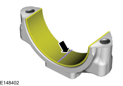 |
-
NOTE: Do not turn the crankshaft during this step.
Install and tighten to specifications, then remove the connecting rod bearing cap.
-
Measure the Plastigage to get the connecting rod bearing
journal clearance. The Plastigage should be smooth and flat. A changing
width indicates a tapered or damaged connecting rod or connecting rod
bearing.
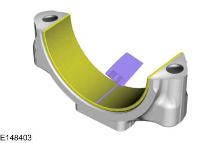 |
 General Procedures - Compression and Cylinder Leakage Test
Make sure the oil in the crankcase is of the correct
viscosity and at the correct level and that the battery is correctly
charged. Operate the vehicle until the engine is at normal operating
temperature...
 General Procedures - Crankshaft Main Bearing Journal Clearance
Check
NOTE:
Refer to the appropriate Section 303-01 for the specification.
NOTE:
Crankshaft main bearing journals must be within specifications before checking journal clearance...
Other information:
Ford Ecosport 2014-2026 Service and Repair Manual: Removal and Installation - Subwoofer Speaker
Removal Remove the RH loadspace trim panel. Refer to: Loadspace Trim Panel (501-05 Interior Trim and Ornamentation, Removal and Installation). Remove the screws, disconnect the electrical connector and remove the subwoofer speaker...
Ford Ecosport 2014-2026 Service and Repair Manual: Description and Operation - Airbag and Seatbelt Pretensioner Supplemental Restraint System (SRS) - Vehicles With: Rear Seat Side Airbag - Component Location
Item Description 1 LH and RH front impact severity sensors 2 BECMB 3 Passenger front door side impact sensor 4 OCSM (includes OCS sensor and gel-filled bladder) 5 PAD indicator 6 RCM 7 Front passenger seatbelt buckle (includes buckle sensor) 8 Driver and passenger..
Categories
- Manuals Home
- 2nd Gen Ford Ecosport Service Manual (2014 - 2026)
- Removal and Installation - Body Control Module (BCM)
- General Procedures - Battery Charging
- Diagnosis and Testing - Evaporative Emissions
- Specifications
- Diagnosis and Testing - Body Control Module (BCM)
Removal and Installation - Rear Halfshaft Seal
Special Tool(s) / General Equipment
 205-153
(T80T-4000-W)
205-153
(T80T-4000-W)
Handle
 205-990
Installer, Axle Seal
TKIT-2012A-FL
TKIT-2012A-ROW

Copyright © 2026 www.foecosport2.com