Ford Ecosport: Supplemental Restraint System / General Procedures - Clockspring Adjustment
Special Tool(s) / General Equipment
| Adhesive Tape |
 WARNING:
If the clockspring is not correctly centralized, it may fail
prematurely. If in doubt, repeat the centralizing procedure. Failure to
follow these instructions may increase the risk of serious personal
injury or death in a crash.
WARNING:
If the clockspring is not correctly centralized, it may fail
prematurely. If in doubt, repeat the centralizing procedure. Failure to
follow these instructions may increase the risk of serious personal
injury or death in a crash.
NOTE: Typical SCCM and clockspring shown, others similar.
-
Refer to: Pyrotechnic Device Health and Safety Precautions (100-00 General Information, Description and Operation).
WARNING:
Before beginning any service procedure in this section,
refer to Safety Warnings in section 100-00 General Information. Failure
to follow this instruction may result in serious personal injury.
-
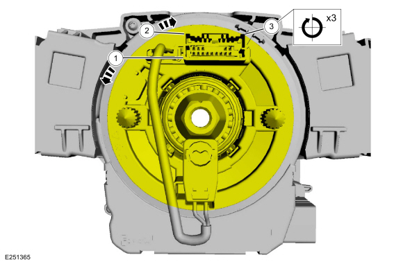
NOTICE: Do not over-rotate the clockspring inner rotor. The internal ribbon wire is connected to the clockspring rotor. The internal ribbon wire acts as a stop and can be broken from its internal connection. Failure to follow this instruction may result in component damage and/or system failure.
-
Turn the clockspring rotor counterclockwise, carefully feeling for resistance to turning.
-
Turn the clockspring rotor clockwise so the electrical connector is in the 12 o'clock position.
-
NOTE: After final positioning, do not allow the clockspring rotor to rotate from this position.
Turn the clockspring rotor clockwise through 3 complete turns ending with the clockspring rotor electrical connector in the 12 o'clock position.
-
Turn the clockspring rotor counterclockwise, carefully feeling for resistance to turning.
 |
-
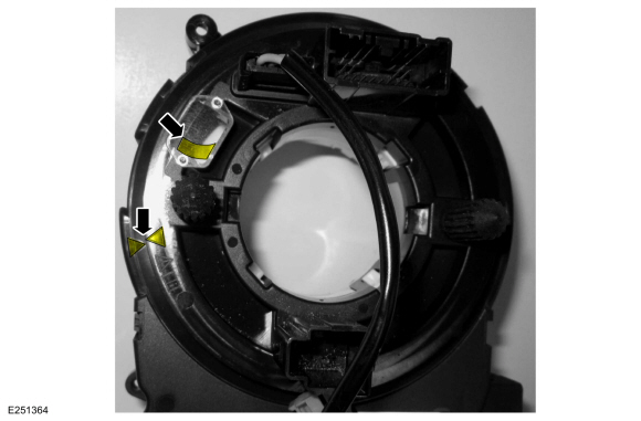
When the clockspring is correctly centralized, the wire
harness is visible through the site glass and the 2 arrows at the LH
side are aligned. Make sure the clockspring does not rotate from this
position until after the steering wheel is installed.
 |
-
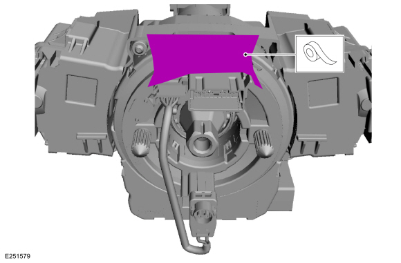
Tape the clockspring rotor to the outer housing to keep it from rotating.
Use the General Equipment: Adhesive Tape
 |

 General Procedures - Inspection and Repair after a Supplemental Restraint System (SRS) Deployment
Inspection
WARNING:
If a vehicle has been in a crash, inspect the Restraints
Control Module (RCM) and impact sensor mounting areas for any damage or
deformation...
Other information:
Ford Ecosport 2014-2026 Service and Repair Manual: General Procedures - Front Fog Lamp Adjustment
Adjustment NOTE: Horizontal aim is not adjustable. Consult your state vehicle inspection center for recommended tolerance ranges for visual aiming. NOTE: Before starting fog lamp adjustment, entry conditions must be met. Vehicle must be on level ground...
Ford Ecosport 2014-2026 Service and Repair Manual: Description and Operation - Anti-Lock Brake System (ABS) and Stability Control - System Operation and Component Description
System Operation System Diagram Item Description 1 HCU 2 PCM 3 IPC 4 ABS module 5 RCM 6 PSCM 7 BCM 8 LH Front wheel speed sensor 9 RH Front wheel speed sensor 10 LH Rear wheel speed sensor 11 LH Rear whe..
Categories
- Manuals Home
- 2nd Gen Ford Ecosport Service Manual (2014 - 2026)
- Engine
- Body and Paint
- Description and Operation - Jacking and Lifting - Overview
- Diagnosis and Testing - Body Control Module (BCM)
- Diagnosis and Testing - Evaporative Emissions
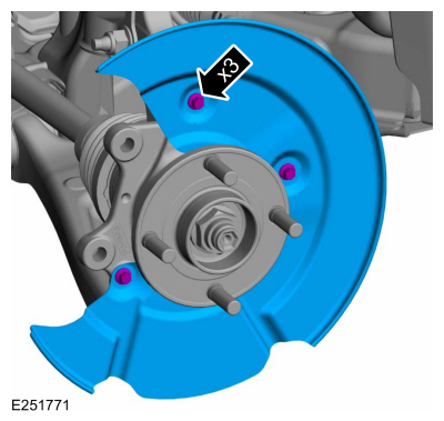
Removal and Installation - Brake Disc Shield
Removal
NOTE: Removal steps in this procedure may contain installation details.
Remove the brake disc.Refer to: Brake Disc (206-03 Front Disc Brake, Removal and Installation).
Remove the bolts and brake disc.
Torque: 80 lb.in (9 Nm)