Ford Ecosport: Rear Suspension - FWD / Disassembly and Assembly - Rear Shock Absorber
Materials
| Name | Specification |
|---|---|
| Grease - Silicone | ESA-M1C200-A |
DISASSEMBLY
NOTICE: Suspension fasteners are critical parts that affect the performance of vital components and systems. Failure of these fasteners may result in major service expense. Use the same or equivalent parts if replacement is necessary. Do not use a replacement part of lesser quality or substitute design. Tighten fasteners as specified.
NOTE: Disassembly steps in this procedure may contain assembly details.
NOTE: Typical assembly shown. actual application may vary.
-
Remove the rear shock absorber.
Refer to: Rear Shock Absorber (204-02A Rear Suspension - FWD, Removal and Installation).
-
-
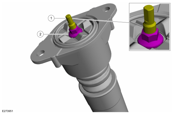
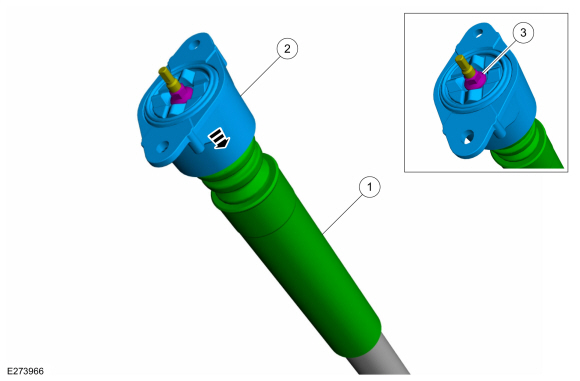
NOTICE: Do not use an impact wrench on the rear shock absorber inner rod nut.
NOTE: Use the hex-holding feature to prevent the shock absorber inner rod from rotating while removing and installing the shock absorber nut.
Lock the rear shock absorber inner rod.
-
Remove the rear shock absorber nut.
-
 |
-
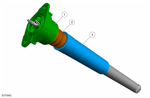
NOTICE: Do not use an impact wrench on the rear shock absorber inner rod nut.
NOTE: Note the position of the components before disassembly.
-
Remove the shock absorber top mount.
-
Remove the jounce bumper.
-
Remove the dust shield.
-
Remove the shock absorber top mount.
 |
-
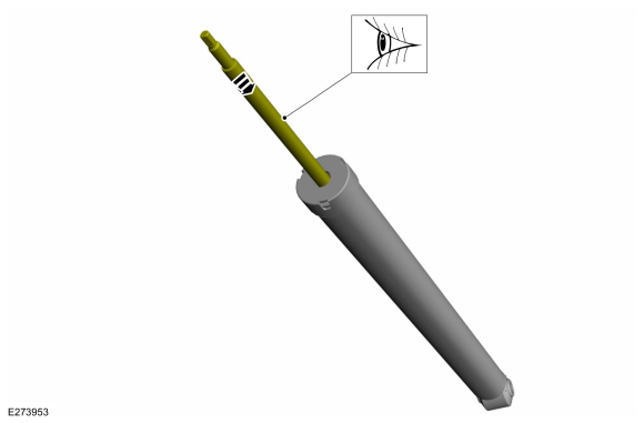
Inspect the shock absorber inner rod and push the rod into the cylinder.
 |
ASSEMBLY
NOTE: Make sure that the components are installed to the position noted before removal.
-
To assemble, reverse the disassembly procedure.
-
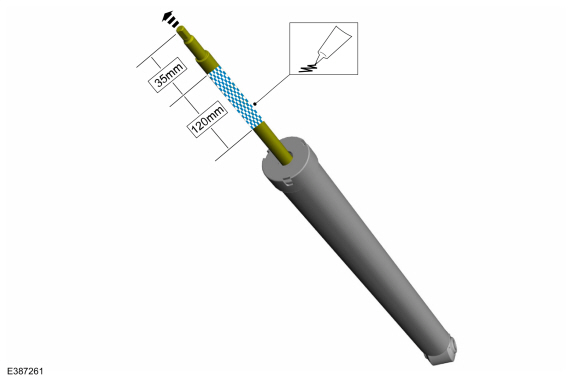
NOTICE: Take extra care not to damage the piston rod surface.
NOTE: Make sure the grease is applied completely around the shock absorber inner rod. Do not allow grease to make contact with the shock absorber rod threads.
NOTE: Avoid excess grease application, which can seep from the rod onto the outer can of the damper. A customer may misinterpret excess grease seepage as an oil leak from damper (false leak).
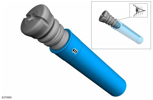
Wearing rubber gloves, use a finger to move the specified grease material around the piston rod along the length of the shock absorber rod that makes contact with the jounce bumper plus an additional 15 mm (0.5 in). Grease quantity of approx. 0.3g to 0.5g. Replace the dust tube and jounce bumper assembly in a twisting motion to further distribute the grease.
Material: Grease - Silicone (ESA-M1C200-A)
 |
-
NOTICE: Make sure the components are correctly aligned during assembly.
Assemble the dust shield into jounce bumper.
 |
-
-
Install the jounce bumper and dust shield assembly.
-
Install the shock absorber top mount.
-
NOTICE: Do not use an impact wrench on the rear shock absorber inner rod nut.
NOTE: Utilize the hex holding feature to prevent the shock absorber inner rod from turning while installing the shock absorber inner rod nut.
Install and tighten the new rear shock absorber nut.
Torque: 159 lb.in (18 Nm)
-
Install the jounce bumper and dust shield assembly.
 |
-
Install the rear shock absorber.
Refer to: Rear Shock Absorber (204-02A Rear Suspension - FWD, Removal and Installation).
 Removal and Installation - Wheel Hub - Vehicles With: Rear Disc Brakes
Removal
NOTICE:
Suspension fasteners are critical parts that affect the
performance of vital components and systems. Failure of these fasteners
may result in major service expense...

Other information:
Ford Ecosport 2014-2026 Service and Repair Manual: Diagnosis and Testing - Low/Reverse Clutch Assembly
Low/Reverse Clutch For low/reverse clutch operation, REFER to: Transmission Description - System Operation and Component Description (307-01B Automatic Transmission - 6-Speed Automatic Transmission – 6F35, Description and Operation). REFER to: Transmission Description (307-01B Automatic Transmission - 6-Speed Automatic Transmission – 6F35, Description and Operation). REFER to: Lo..
Ford Ecosport 2014-2026 Service and Repair Manual: General Procedures - Supplemental Restraint System (SRS) Depowering
Depower WARNING: Incorrect repair techniques or actions can cause an accidental Supplemental Restraint System (SRS) deployment. Never compromise or depart from these instructions. Failure to precisely follow all instructions could result in serious personal injury from an accidental deployment. WARNING: Before beginning any service procedure in thi..
Categories
- Manuals Home
- 2nd Gen Ford Ecosport Service Manual (2014 - 2026)
- Removal and Installation - Blower Motor
- Removal and Installation - Front Seat
- Description and Operation - Jacking and Lifting - Overview
- Removal and Installation - Fuel Pump and Sender Unit
- Removal and Installation - Roof Rail
Disassembly - Engine
Special Tool(s) / General Equipment
 205-153
(T80T-4000-W)
205-153
(T80T-4000-W)
Handle
 303-103
(T74P-6375-A)
303-103
(T74P-6375-A)
Holding Tool, Flywheel
T74P-77000-A
TKIT-2009TC-F
 303-1247
VCT Spark Plug Tube Seal Remover and Installer
TKIT-2006UF-FLM
TKIT-2006UF-ROW
 303-15