Ford Ecosport: Automatic Transmission - 6-Speed Automatic Transmission – 6F35 / Disassembly and Assembly of Subassemblies - Transmission Case
Ford Ecosport 2014-2026 Service and Repair Manual / Automatic Transmission / Automatic Transmission - 6-Speed Automatic Transmission – 6F35 / Disassembly and Assembly of Subassemblies - Transmission Case
Special Tool(s) / General Equipment
 |
205-153
(T80T-4000-W)
Handle |
 |
206-084 Installer, Wheel Speed Sensor Ring TKIT-2003-FLM/LM TKIT-2003D-F |
 |
307-664 Case Bushing Installer TKIT-2009OP-FLM TKIT-2009OP-ROW |
| Flat Headed Screw Driver | |
| Hydraulic Press | |
Materials
| Name | Specification |
|---|---|
| Loctite® 648 1835922 |
WSK-M2G349-A4 |
DISASSEMBLY
-
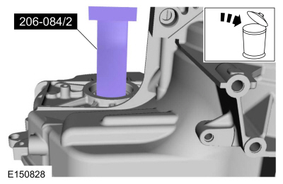
NOTE: The transmission case bushing should only be removed if the bushing is damaged.
NOTE: Press the bushing out of the transmission case from the outside to the inside so the transmission case rests on a flat surface.
If necessary, use the special tools to remove and discard the LH transmission case bushing from the transmission case.
Use Special Service Tool: 206-084 Installer, Wheel Speed Sensor Ring.
Use the General Equipment: Hydraulic Press
 |
-
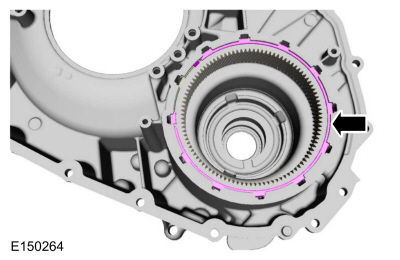
Remove the differential ring gear snap ring.
 |
-
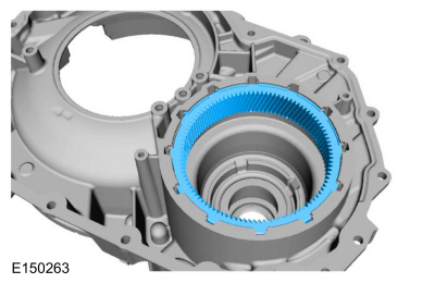
Remove the differential ring gear.
 |
ASSEMBLY
-
Install the differential ring gear in the torque converter housing.
|
-
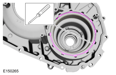
NOTICE: Be sure the flat side of the beveled snap ring is facing down or the ring can come loose, causing damage to the transmission.
Install the beveled differential ring gear snap ring with the flat side facing down.
|
-
NOTE: Make sure the snap ring is seated in the groove.
Seat the snap ring.
Use the General Equipment: Flat Headed Screw Driver
 |
-
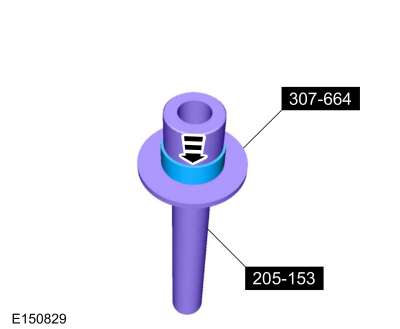
If the transmission case bushing was removed, install a new bushing on the special tool.
Use Special Service Tool: 205-153 (T80T-4000-W) Handle. , 307-664 Case Bushing Installer.
 |
-
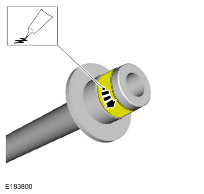
Place a small amount of Retaining Compound on only the
outside of the entire outer circumference of the new red Teflon® coated
bushing before installation.
Material: Loctite® 648 / 1835922 (WSK-M2G349-A4)
 |
-
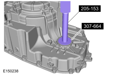
Using the special tool, install the new bushing in the transmission case.
Use Special Service Tool: 205-153 (T80T-4000-W) Handle. , 307-664 Case Bushing Installer.
Use the General Equipment: Hydraulic Press
 |


Other information:
Ford Ecosport 2014-2026 Service and Repair Manual: Diagnosis and Testing - Pinpoint Test - DTC: AU, Vehicles With: Rear Seat Side Airbag
B140A:11, B140A:12, B140A:13, B140A:1A Refer to Wiring Diagrams Cell 46 for schematic and connector information. Normal Operation and Fault Conditions The RCM continuously monitors the driver second row side airbag circuits for the following faults: Resistance out of range Unexpected voltage Short to ground Faulted driver second row side airbag ..
Ford Ecosport 2014-2026 Service and Repair Manual: Removal and Installation - Condenser - 2.0L Duratec-HE (129kW/175PS)
Removal NOTICE: During the removal or installation of components, cap, tape or otherwise appropriately protect all openings and tubes/fittings to prevent the ingress of dirt or other contamination. Remove caps, tape and other protective materials prior to installation. NOTE: Removal steps in this procedure may contain installation details. Remove the radiator..
Categories
- Manuals Home
- 2nd Gen Ford Ecosport Service Manual (2014 - 2026)
- Service Information
- Removal and Installation - Fuel Pump and Sender Unit
- General Procedures - Battery Charging
- Automatic Transmission - 6-Speed Automatic Transmission – 6F35
- Removal and Installation - Catalytic Converter
Removal and Installation - Oil Pressure Switch
Materials
Name Specification Motorcraft® Thread Sealant with PTFETA-24-B WSK-M2G350-A2
Removal
NOTE: Removal steps in this procedure may contain installation details.
With the vehicle in NEUTRAL, position it on a hoist.Refer to: Jacking and Lifting - Overview (100-02 Jacking and Lifting, Description and Operation).
If equipped, remove the bolts and the underbody shield.
Copyright © 2026 www.foecosport2.com