Ford Ecosport: Rear Suspension - AWD / Description and Operation - Rear Suspension - Overview
Overview
The rear suspension consists of the following components:
- Coil springs
- Upper and lower arms
- Shock absorbers
- Stabilizer bar and links
- Wheel bearing and wheel hub assemblies
- Wheel knuckles
- Wheel studs
- Differential carrier and trailing arm bushes
The rear suspension uses 2 parallel arms (1 upper and 1 lower). Each arm has a mounting position to the differential carrier and an attachment at the wheel knuckle. This suspension allows the wheels to react to road imperfections independent of each other. The shock absorber mounts to the lower arm and along with the spring, controls vertical movement. The stabilizer bar and links control suspension lean/sway.

 Removal and Installation - Wheel Bearing and Wheel Hub - Vehicles With: Rear Drum Brakes
Special Tool(s) /
General Equipment
204-161
(T97P-1175-A)
Installer, HalfshaftTKIT-1997-LM2TKIT-1997-F/FM2TKIT-1997-FLM2
204-348/3Remover/Installer, Wheel Hub/Wheel Bearing
205-D070
(D93P-1175-B)
Remover, Front Wheel Hub
308-095Installer, Input Shaft Bearing
308-604Installer, Output Drive Flange Seal
308-643Installer, Input..
Other information:
Ford Ecosport 2014-2026 Service and Repair Manual: Removal and Installation - Front Door Speaker
Removal NOTE: Removal steps in this procedure may contain installation details. Remove the front door trim panel. Refer to: Front Door Trim Panel (501-05 Interior Trim and Ornamentation, Removal and Installation). Disconnect the electrical connector, remove the screws and the front door speaker. Installation ..
Ford Ecosport 2014-2026 Service and Repair Manual: Removal and Installation - Crankshaft Position (CKP) Sensor
Special Tool(s) / General Equipment 303-1521Alignment Tool, Crankshaft Position SensorTKIT-2010C-FLM 303-507Timing Peg, Crankshaft TDCTKIT-2001N-FLMTKIT-2001N-ROW Ford Diagnostic Equipment Removal NOTE: Do not loosen or remove the crankshaft pulley bolt without first installing the special tools as instructed in this procedure. The crankshaft pu..
Categories
- Manuals Home
- 2nd Gen Ford Ecosport Service Manual (2014 - 2026)
- Removal and Installation - Body Control Module (BCM)
- General Procedures - Transmission Fluid Level Check
- Removal and Installation - Fuel Pump and Sender Unit
- Diagnosis and Testing - Body Control Module (BCM)
- General Procedures - Battery Charging
Removal and Installation - Steering Column Shaft
Removal
NOTE: Removal steps in this procedure may contain installation details.
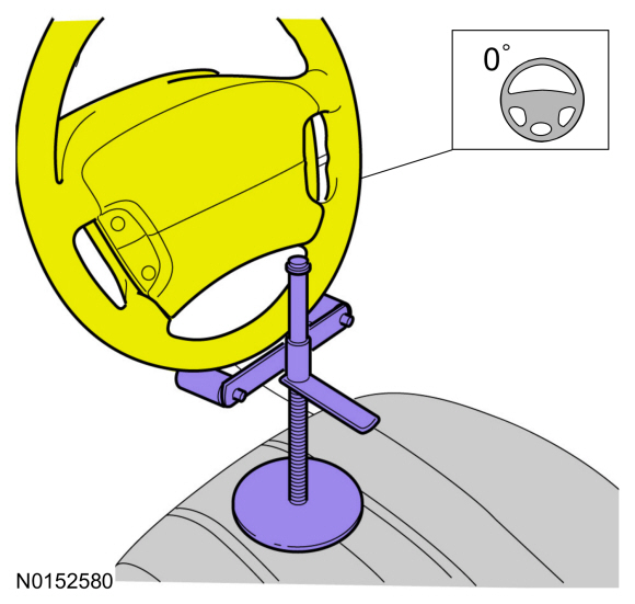
NOTICE: Do not allow the steering column to rotate while the steering column shaft is disconnected or damage to the steering column internal sensor may result.
NOTE: Use a steering wheel holding device (such as Hunter® 28-75-1 or equivalent)
Hold the steering wheel in the straight-ahead position.