Ford Ecosport: Four-Wheel Drive Systems / Description and Operation - Four-Wheel Drive Systems - System Operation and Component Description
System Operation
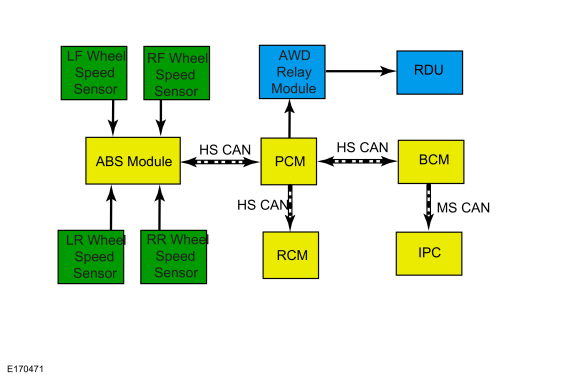
System Diagram

| Item | Description |
|---|---|
| 1 | PCM |
| 2 | HS-CAN |
| 3 | Active Torque Coupling (ATC) solenoid (integral to the Rear Drive Unit (RDU) |
| 4 | BCM |
| 5 | IPC |
| 6 | RCM |
| 7 | ABS module |
| 8 | HS-CAN |
| 9 | HS-CAN |
| 10 | MS-CAN |
| 11 | AWD relay module |
| 12 | LH rear wheel speed sensor |
| 13 | RH rear wheel speed sensor |
| 14 | RH front wheel speed sensor |
| 15 | LH front wheel speed sensor |
Network Message Chart
Module Network Input MessagesPCM
| Broadcast Message | Originating Module | Message Purpose |
| Vehicle yaw rate | RCM | The PCM uses lateral acceleration and yaw rate information for the four-wheel drive system to determine percentage of torque to be transferred to the rear wheels. |
| Wheel speed data | ABS module | The PCM uses wheel speed information for the four-wheel drive system to determine percentage of torque to be transferred to the rear wheels. |
| Accelerator pedal position | PCM | The PCM uses pedal information for the four-wheel drive system to determine percentage of torque to be transferred to the rear wheels. |
Spare Tire And Mismatched Tire Sizes
If the spare tire is installed, the AWD system may disable automatically and enter FWD only mode to protect driveline components. This condition may be indicated by AWD OFF message in the message center. If there is a Check AWD message in the message center from using the spare tire, this indicator should turn off after reinstalling the repaired or replaced normal road tire and cycling the ignition OFF and ON. It is recommended to reinstall the repaired or replaced road tire as soon as possible. Major dissimilar tire sizes between the front and rear axles could cause the AWD system to stop functioning and default to FWD or damage the AWD system. If this condition occurs, a DTC is set and a Check AWD message is displayed on the message center.
AWD Control And Fault Indicators
The AWD system consists of a transfer case, driveshaft, front and rear halfshafts, AWD relay module, Rear Drive Unit (RDU) with integral Active Torque Coupling (ATC) solenoid, and includes the PCM for AWD control logic. Using inputs from various module/systems, the PCM sends a command to the AWD relay module which controls the amount of torque sent to the rear wheels by sending a PWM duty cycle to the Active Torque Coupling (ATC) solenoid. AWD system faults are indicated by a driveline icon indicator in the IPC as well as the Check AWD message in the message center.
AWD Bar Code Identification
The AWD system on this vehicle is equipped with an Active Torque Coupling (ATC) solenoid to reduce the tolerance of electrical current to torque delivered to the Active Torque Coupling (ATC) solenoid. The Active Torque Coupling (ATC) solenoid has a bar code label that can be found on the bottom of the Rear Drive Unit (RDU). The PCM uses this bar code information to match the clutch characteristics of the Active Torque Coupling (ATC) solenoid with the desired output torque. If the bar code information does not match the PCM information, driveline damage or driveability concerns can occur. Therefore, if the PCM is replaced, the new PCM must be configured with the existing Active Torque Coupling (ATC) solenoid bar code information. If the Rear Drive Unit (RDU) is replaced, the existing PCM must be configured with the new Active Torque Coupling (ATC) solenoid bar code information. Also, for PCM or Rear Drive Unit (RDU) replacement the AWD Drive Cycle must be performed after the Automatic Torque Coupling Configuration.
Automatic Torque Coupling Configuration Bar Code Label
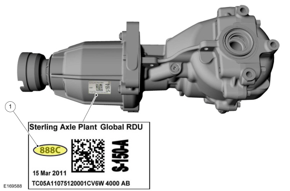
| Item | Description |
| 1 | Active Torque Coupling (ATC) solenoid bar code label |
Automatic Torque Coupling Configuration
NOTICE: If the Active Torque Coupling (ATC) solenoid bar code information is not correct, Rear Drive Unit (RDU) damage or driveability concerns can occur.
NOTE: The 4-digit alpha numeric bar code is located on the label attached to the Rear Drive Unit (RDU).
1. Using a diagnostic scan tool, perform the Automatic Traction Coupling Barcode Entry procedure. This procedure is located within Powertrain, under the toolbox icon. Follow the instructions displayed on the diagnostic scan tool.
NOTE: If the PCM was not replaced, the barcode information is already populated. If the information is different it must be changed to match the label on the Rear Drive Unit (RDU).
NOTE: The diagnostic scan tool verifies the digits entered are valid and displays a message if the information is not valid.
2. Verify and if necessary, change the barcode information to match the label on the Rear Drive Unit (RDU).
3. Carry out the AWD Drive Cycle after downloading the Active Torque Coupling (ATC) solenoid bar code information to the PCM .
AWD Drive Cycle
NOTE: Always drive the vehicle in a safe manner according to driving conditions and obey all traffic laws.
1. Carry out 3 accelerations from 0-30 mph (0-48 km/h) in a straight line.
- Perform this procedure at low, medium and full accelerator pedal position.
- Verify there is no perceived front wheel slip.
2. On dry pavement, drive the vehicle at 5 mph (8 km/h) in a fully locked turn.
- Verify there is no driveline binding.
Component Description
PCM
The PCM is the logic module for the four-wheel drive system. Multiple modules/system inputs are used for the four-wheel drive system to determine the percentage of torque to be transferred to the rear wheels.
Transfer Case
The
transfer case is a gearbox that attaches to the transmission. The
transfer case directs power to the rear driveshaft and the Rear Drive
Unit (RDU). For more information on the transfer case,
Refer to: Transfer Case - Overview (308-07B Transfer Case - 6-Speed Automatic Transmission – 6F35, Description and Operation).
AWD Relay Module
The AWD relay module receives the command from the PCM , and in turn supplies a PWM output to the Automatic Torque Coupling (ATC) solenoid for the requested torque to be applied.
Automatic Torque Coupling (ATC) Solenoid
The
Automatic Torque Coupling (ATC) solenoid is integral to the Rear Drive
Unit (RDU), and applies clutch pressure as controlled by the AWD
relay module to increase or decrease torque to the rear wheels. The
Rear Drive Unit (RDU) transfers torque from the drive shaft to the rear
wheels depending on the specific request from the AWD module. The Rear
Drive Unit (RDU) and Automatic Torque Coupling (ATC) solenoid are
serviced in Chassis, Driveline section.
Refer to: Axle Assembly (205-02 Rear Drive Axle/Differential, Removal and Installation).
 Description and Operation - Four-Wheel Drive Systems - Overview
The AWD system consists of the following:
Power Transfer Unit (PTU)
Rear driveshaft
AWD relay module
Rear axle with coupling device
Torque
from the engine is transferred through the transmission to the Power
Transfer Unit (PTU)...
 Diagnosis and Testing - Four-Wheel Drive Systems
DTC Chart: AWD System - PCM
Diagnostics in this manual assume a certain skill level and knowledge of Ford-specific diagnostic practices. REFER to: Diagnostic Methods (100-00 General Information, Description and Operation)...
Other information:
Ford Ecosport 2014-2025 Service and Repair Manual: Description and Operation - Engine Component View
Engine — External Components Item Part Number Description 1 85098509 Coolant pump pulley 2 9C3749C374 High-pressure fuel pump noise insulator 3 9D3769D376 High-pressure fuel pump 4 9B3749B374 High-pressure fuel pump drive unit 5 8K5568K556 Coolant outlet 6 9F7979F797 Fuel..
Ford Ecosport 2014-2025 Service and Repair Manual: Diagnosis and Testing - Pinpoint Test - DTC: R, Vehicles With: Rear Seat Side Airbag
B11CF:11, B11CF:12, B11CF:13, B11CF:1A Refer to Wiring Diagrams Cell 46 for schematic and connector information. Normal Operation and Fault Conditions The RCM continuously monitors the passenger airbag adaptive canister vent circuits for the following faults: Resistance out of range Unexpected voltage Short to ground Faulted passenger airbag adapt..
Categories
- Manuals Home
- 2nd Gen Ford Ecosport Service Manual (2014 - 2025)
- Removal and Installation - Body Control Module (BCM)
- Engine
- Removal and Installation - Rear Bumper
- Removal and Installation - Fuel Pump and Sender Unit
- Diagnosis and Testing - Evaporative Emissions
Removal and Installation - Front Brake Flexible Hose
Removal
Remove the wheel and tire.Refer to: Wheel and Tire (204-04A Wheels and Tires, Removal and Installation).
Remove the brake flexible hose bracket bolt.
Disconnect the brake tube fitting and remove the brake hose clip.
Loosen the brake hose fitting and remove the brake flexible hose.