Ford Ecosport: Supplemental Restraint System / Diagnosis and Testing - Pinpoint Test - DTC: R, Vehicles With: Rear Seat Side Airbag
B11CF:11, B11CF:12, B11CF:13, B11CF:1A
Refer to Wiring Diagrams Cell 46 for schematic and connector information.
Normal Operation and Fault Conditions
The RCM continuously monitors the passenger airbag adaptive canister vent circuits for the following faults:
- Resistance out of range
- Unexpected voltage
- Short to ground
- Faulted passenger airbag adaptive canister vent
If a fault is detected, the RCM stores DTC B11CF:11, B11CF:12, B11CF:13 or B11CF:1A in memory and sends a message to the IPC to illuminate the airbag warning indicator.
The RCM analyzes the deployment loop resistance to determine if a fault exists. The value displayed in the PID is the deployment loop resistance measured by the RCM . If the value displayed is lower or higher than the desired range (refer to diagram below), the RCM can set a DTC . As the deployment loop resistance drifts farther outside the desired range, the chance for a DTC increases. Small variations in resistance can occur due to the effect of road vibrations on terminal fit. Crimps and terminals can be affected by stress and harness movement and can cause an increase in resistance due to wire strain. These variables can result in an intermittent fault. For this reason, the test requires the PID value to be within the desired range before the fault is considered repaired, regardless if the module is reporting an on-demand DTC at the time of diagnosis. Following this direction helps make sure that minor changes in resistance do not create a repeat concern. This test uses process of elimination to diagnose each part of the deployment loop circuit including:
- Wiring
- Connections
- Passenger airbag adaptive canister vent
- RCM
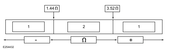
| Item | Description |
|---|---|
| 1 | May set DTC |
| 2 | Desired range |
DTC Fault Trigger Conditions
| DTC | Description | Fault Trigger Conditions |
|---|---|---|
| B11CF:11 | Passenger Frontal Airbag Canister Vent: Circuit Short to Ground | A fault is indicated when the RCM senses a short to ground on either passenger airbag adaptive canister vent circuit for more than 6 seconds. |
| B11CF:12 | Passenger Frontal Airbag Canister Vent: Circuit Short to Battery | A fault is indicated when the RCM senses a short to voltage on either passenger airbag adaptive canister vent circuit for more than 6 seconds. |
| B11CF:13 | Passenger Frontal Airbag Canister Vent: Circuit Open | A fault is indicated when the RCM measures more than the desired resistance between the passenger airbag adaptive canister vent circuits for more than 6 seconds. |
| B11CF:1A | Passenger Frontal Airbag Canister Vent: Circuit Resistance Below Threshold | A fault is indicated when the RCM measures less than the desired resistance between the passenger airbag adaptive canister vent circuits for more than 6 seconds. |
Possible Sources
- Wiring, terminals or connectors
- Passenger airbag adaptive canister vent
- RCM
PINPOINT TEST A: B11CF:11, B11CF:12, B11CF:13 AND B11CF:1A
 WARNING:
Incorrect repair techniques or actions can cause an
accidental Supplemental Restraint System (SRS) deployment. Never
compromise or depart from these instructions. Failure to precisely
follow all instructions could result in serious personal injury from an
accidental deployment.
WARNING:
Incorrect repair techniques or actions can cause an
accidental Supplemental Restraint System (SRS) deployment. Never
compromise or depart from these instructions. Failure to precisely
follow all instructions could result in serious personal injury from an
accidental deployment.
|
|||||||||||||
| NOTICE: Use the correct probe adapter(s) when making measurements. Failure to use the correct probe adapter(s) may cause damage to the connector. | |||||||||||||
| NOTE: Most faults are due to connector and/or wiring concerns. Carry out a thorough inspection and verification before proceeding with the pinpoint test. | |||||||||||||
| NOTE: Only disconnect or reconnect SRS components when instructed to do so within a pinpoint test step. Failure to follow this instruction may result in incorrect diagnosis of the SRS . | |||||||||||||
| NOTE: Always make sure the correct SRS component is being installed. Parts released for other vehicles may not be compatible even if they appear physically similar. Check the part number listed in the Ford parts catalog to make sure the correct component is being installed. If an incorrect SRS component is installed, Diagnostic Trouble Codes (DTCs) may set. | |||||||||||||
| NOTE: The SRS must be fully operational and free of faults before releasing the vehicle to the customer. | |||||||||||||
| A1 RETRIEVE RCM (RESTRAINTS CONTROL MODULE) DIAGNOSTIC TROUBLE CODES (DTCS) | |||||||||||||
Was DTC B11CF:11, B11CF:12, B11CF:13 and B11CF:1A retrieved on-demand during self-test?
|
|||||||||||||
| A2 CHECK THE PASSENGER FRONTAL AIRBAG CAN VENT CONTROL (DEPLOY_08_R) PID (PARAMETER IDENTIFICATION) | |||||||||||||
Does the PID value read between 1.44 and 3.52 ohms?
|
|||||||||||||
| A3 CHECK THE PASSENGER FRONTAL AIRBAG CAN VENT CONTROL (DEPLOY_08_R) PID (PARAMETER IDENTIFICATION) WHILE CARRYING OUT THE HARNESS TEST | |||||||||||||
Does the PID value read between 1.44 and 3.52 ohms while carrying out the harness test?
|
|||||||||||||
| A4 CHECK THE PASSENGER AIRBAG ADAPTIVE CANISTER VENT DEPLOYMENT CONTROL DTC (DIAGNOSTIC TROUBLE CODE) FOR A FAULT STATUS CHANGE (LOW RESISTANCE INDICATED) | |||||||||||||
|
NOTE: This pinpoint test step attempts to change the fault reported by the RCM by inducing a different fault condition. If the reported fault changes, this indicates the RCM is functioning correctly and is not the source of the fault.
Did the on-demand DTC change from B11CF:1A to B11CF:13?
|
|||||||||||||
| A5 CHECK FOR A SHORT BETWEEN THE PASSENGER AIRBAG ADAPTIVE CANISTER VENT CIRCUITS | |||||||||||||
Is the resistance greater than 10,000 ohms?
|
|||||||||||||
| A6 CHECK THE PASSENGER AIRBAG ADAPTIVE CANISTER VENT CIRCUITS FOR AN OPEN | |||||||||||||
Are the resistances less than 0.5 ohm?
|
|||||||||||||
| A7 CHECK THE PASSENGER AIRBAG ADAPTIVE CANISTER VENT DEPLOYMENT CONTROL DTC (DIAGNOSTIC TROUBLE CODE) FOR A FAULT STATUS CHANGE (OPEN INDICATED) | |||||||||||||
|
NOTE: This pinpoint test step attempts to change the fault reported by the RCM by inducing a different fault condition. If the reported fault changes, this indicates the RCM is functioning correctly and is not the source of the fault.
Did the on-demand DTC change from B11CF:13 to B11CF:1A?
|
|||||||||||||
| A8 CHECK THE PASSENGER AIRBAG ADAPTIVE CANISTER VENT DEPLOYMENT CONTROL DTC (DIAGNOSTIC TROUBLE CODE) FOR A FAULT STATUS CHANGE (SHORT TO GROUND INDICATED) | |||||||||||||
|
NOTE: This pinpoint test step attempts to change the fault reported by the RCM by inducing a different fault condition. If the reported fault changes, this indicates the RCM is functioning correctly and is not the source of the fault.
Did the on-demand DTC change from B11CF:11 to B11CF:13?
|
|||||||||||||
| A9 CHECK THE PASSENGER AIRBAG ADAPTIVE CANISTER VENT CIRCUITS FOR A SHORT TO GROUND | |||||||||||||
Are the resistances greater than 10,000 ohms?
|
|||||||||||||
| A10 CHECK THE PASSENGER AIRBAG ADAPTIVE CANISTER VENT CIRCUITS FOR A SHORT TO VOLTAGE | |||||||||||||
Is any voltage present?
|
|||||||||||||
| A11 CONFIRM THE PASSENGER AIRBAG ADAPTIVE CANISTER VENT FAULT | |||||||||||||
|
NOTE: Make sure all SRS components and the RCM electrical connectors are connected before carrying out the self-test. If not, Diagnostic Trouble Codes (DTCs) are recorded.
Was the original DTC retrieved on-demand during self-test?
|
|||||||||||||
| A12 CONFIRM THE RCM (RESTRAINTS CONTROL MODULE) FAULT | |||||||||||||
|
NOTE: Make sure all SRS components and the RCM electrical connectors are connected before carrying out the self-test. If not, Diagnostic Trouble Codes (DTCs) are recorded.
Was the original DTC retrieved on-demand during self-test?
|
|||||||||||||
| A13 CHECK THE PASSENGER FRONTAL AIRBAG CAN VENT CONTROL (DEPLOY_08_R) PID (PARAMETER IDENTIFICATION) FOR AN INTERMITTENT LOW RESISTANCE OR OPEN CIRCUIT FAULT | |||||||||||||
Does the PID value read between 1.44 and 3.52 ohms?
|
|||||||||||||
| A14 CHECK THE PASSENGER AIRBAG ADAPTIVE CANISTER VENT DEPLOYMENT CONTROL CIRCUITS FOR AN INTERMITTENT SHORT TO GROUND FAULT | |||||||||||||
Was DTC B11CF:11 retrieved on-demand during self-test?
|
|||||||||||||
| A15 CHECK THE PASSENGER AIRBAG ADAPTIVE CANISTER VENT DEPLOYMENT CONTROL CIRCUITS FOR AN INTERMITTENT SHORT TO BATTERY FAULT | |||||||||||||
Was DTC B11CF:12 retrieved on-demand during self-test?
|
|||||||||||||
| A16 CHECK THE HARNESS AND CONNECTORS | |||||||||||||
Were any concerns found?
|
|||||||||||||
| A17 CHECK FOR ADDITIONAL SRS (SUPPLEMENTAL RESTRAINT SYSTEM) DIAGNOSTIC TROUBLE CODES (DTCS) | |||||||||||||
Are any RCM , OCSM and/or BECMB Diagnostic Trouble Codes (DTCs) retrieved on-demand during self-test?
|


 Diagnosis and Testing - Pinpoint Test - DTC: Q, Vehicles With: Rear Seat Side Airbag
B00D5:11, B00D5:12 and B00D5:13
Refer to Wiring Diagrams Cell 46 for schematic and connector information.
Normal Operation and Fault Conditions
The RCM briefly activates each LED in the PAD indicator to prove-out
and verify correct functional operation of the PAD indicator to the
occupants...
 Diagnosis and Testing - Pinpoint Test - DTC: S, Vehicles With: Rear Seat Side Airbag
B11D8:11, B11D8:12, B11D8:13
Refer to Wiring Diagrams Cell 46 for schematic and connector information.
Normal Operation and Fault Conditions
The RCM transmits an event notification signal which communicates
fuel cutoff status and SRS deployment status to the BCM ...
Other information:
Ford Ecosport 2014-2026 Service and Repair Manual: Removal and Installation - Footwell Air Discharge Temperature Sensor
Special Tool(s) / General Equipment Interior Trim Remover Removal NOTE: Removal steps in this procedure may contain installation details. Vehicles with automatic transmission Remove the selector lever trim panel...
Ford Ecosport 2014-2026 Service and Repair Manual: Removal and Installation - Front Seat Track Motor Cable
Removal NOTE: Seat removed for clarity. Position the front seat in the full rearward position. Position the front seat in the full upward position. Using a suitable hex wrench locate the access hole and release the tab and position the front seat track motor upward...
Categories
- Manuals Home
- 2nd Gen Ford Ecosport Service Manual (2014 - 2026)
- General Procedures - Transmission Fluid Level Check
- Removal and Installation - Body Control Module (BCM)
- Specifications
- Diagnosis and Testing - Evaporative Emissions
- Description and Operation - Evaporative Emissions - System Operation and Component Description
Removal and Installation - Brake Disc Shield
Removal
NOTE: Removal steps in this procedure may contain installation details.
Remove the brake disc.Refer to: Brake Disc (206-03 Front Disc Brake, Removal and Installation).
Remove the bolts and brake disc.
Torque: 80 lb.in (9 Nm)