Ford Ecosport: Automatic Transmission - 6-Speed Automatic Transmission – 6F35 / Removal and Installation - Transmission Internal Wiring Harness Frame
Ford Ecosport 2014-2026 Service and Repair Manual / Automatic Transmission / Automatic Transmission - 6-Speed Automatic Transmission – 6F35 / Removal and Installation - Transmission Internal Wiring Harness Frame
Special Tool(s) / General Equipment
 |
307-636 Alignment Pins- Valve Body TKIT-2008ET-FLM TKIT-2008ET-ROW |
Removal
-
Remove the main control cover.
Refer to: Main Control Cover (307-01B Automatic Transmission - 6-Speed Automatic Transmission – 6F35, Removal and Installation).
-
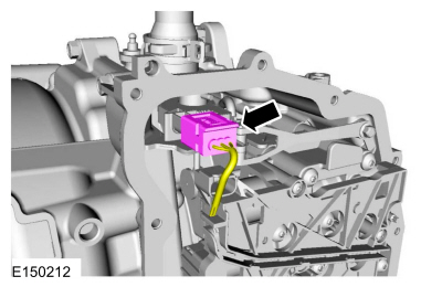
Disconnect the TR sensor electrical connector.
 |
-
Disconnect the OSS sensor electrical connector.
 |
-
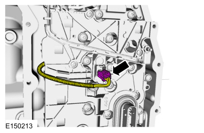
Remove the main control-to-cover seal.
 |
-
NOTICE: Be careful not to bend or twist the transmission internal wiring harness frame or the solenoid terminals when removing the transmission internal wiring harness frame or damage can occur.
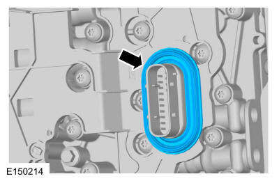
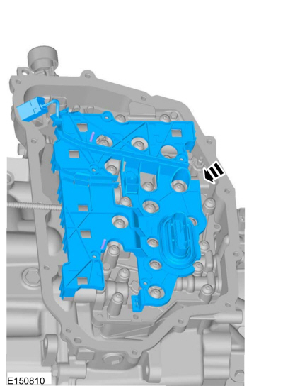
Remove the transmission internal wiring harness frame screws and the transmission internal wiring harness frame from the solenoids by lifting it straight up evenly.
 |
Installation
-
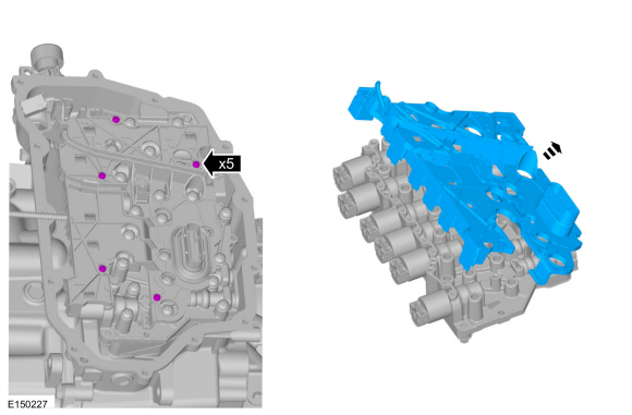
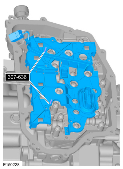
Install the special tools in the solenoid body to align
the transmission internal wiring harness frame during installation.
Use Special Service Tool: 307-636 Alignment Pins- Valve Body.
 |
-
Position the transmission internal wiring harness frame
on the special tools and carefully install the transmission internal
wiring harness frame by pushing straight down into the solenoids.
 |
-
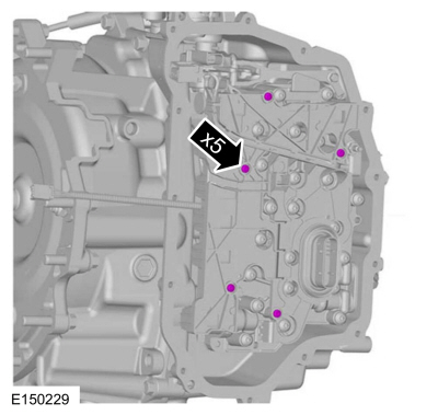
Install the transmission internal wiring harness frame screws.
Torque: 31 lb.in (3.5 Nm)
 |
-
Connect the OSS sensor electrical connector.
|
-
Connect the TR sensor electrical connector.
|
-
Install the main control-to-cover seal.
|
-
Install the main control cover.
Refer to: Main Control Cover (307-01B Automatic Transmission - 6-Speed Automatic Transmission – 6F35, Removal and Installation).
 Removal and Installation - Transmission Fluid Auxiliary Pump
Special Tool(s) /
General Equipment
Hot Air Gun
Removal
With the vehicle in NEUTRAL, position it on a hoist.
Refer to: Jacking and Lifting - Overview (100-02 Jacking and Lifting, Description and Operation)...
 Removal and Installation - Transmission Support Insulator
Special Tool(s) /
General Equipment
303-F072Support Bar, Engine
Materials
Name
Specification
Motorcraft® Threadlock and SealerTA-25-B
-
Motorcraft® Silicone Brake Caliper Grease and Dielectric CompoundXG-3-A
ESA-M1C200-AESE-M1C171-A
Removal
With the vehicle in NEUTRAL, position it on a hoist...
Other information:
Ford Ecosport 2014-2026 Service and Repair Manual: Diagnosis and Testing - Driveshaft
Symptom Chart(s) Diagnostics in this manual assume a certain skill level and knowledge of Ford-specific diagnostic practices. REFER to: Diagnostic Methods (100-00 General Information, Description and Operation). Symptom Chart: NVH Symptom Chart Condition Actions Driveline clunk - loud clunk when shifting from RE..
Ford Ecosport 2014-2026 Service and Repair Manual: Description and Operation - Starting System - System Operation and Component Description
System Operation System Diagram Item Description 1 PCM 2 Starter relay 3 Starter motor 4 BCM 5 Automatic transmission 6 Ignition switch Network Message Chart Module Network Input Messages Powertrain Control Module (PCM) ..
Categories
- Manuals Home
- 2nd Gen Ford Ecosport Service Manual (2014 - 2026)
- Removal and Installation - Roof Rail
- Removal and Installation - Front Seat
- Automatic Transmission - 6-Speed Automatic Transmission – 6F35
- Removal and Installation - Blower Motor
- Description and Operation - Jacking and Lifting - Overview
Removal and Installation - Rear Halfshaft Seal
Special Tool(s) / General Equipment
 205-153
(T80T-4000-W)
205-153
(T80T-4000-W)
Handle
 205-990
Installer, Axle Seal
TKIT-2012A-FL
TKIT-2012A-ROW
Copyright © 2026 www.foecosport2.com