Ford Ecosport: Rear Suspension - FWD / Removal and Installation - Spring
Special Tool(s) / General Equipment
| Spring Compressor | |
| Vise |
Removal
NOTICE: Suspension fasteners are critical parts that affect the performance of vital components and systems. Failure of these fasteners may result in major service expense. Use the same or equivalent parts if replacement is necessary. Do not use a replacement part of lesser quality or substitute design. Tighten fasteners as specified.
NOTE: LH side shown, RH side similar.
NOTE: Removal steps in this procedure may contain installation details.
-
With the vehicle in NEUTRAL, position it on a hoist.
Refer to: Jacking and Lifting - Overview (100-02 Jacking and Lifting, Description and Operation).
-
 WARNING:
Take extra care when handling the compressed spring.
WARNING:
Take extra care when handling the compressed spring.
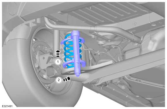
NOTICE: When installing a suitable spring compressor, use care not to damage the spring coating.
Compress the coil spring enough to relieve the tension and remove the spring.
Use the General Equipment: Spring Compressor
Use the General Equipment: Vise
 |
Installation
NOTE: Make sure that the spring is correctly located in the upper and lower spring seat.
-
To install, reverse the removal procedure.
 Description and Operation - Rear Suspension - Overview
Overview
The rear suspension consists of the following components:
Twist-beam axle (torsionally rigid axle)
Coil springs
Shock absorbers
Rear axle bushings
Wheel bearing and wheel hub assemblies
Wheel studs
Characteristics of rear axle:
Single-pipe
gas shock absorbers with stable damping performance for optimum
handling...
 Removal and Installation - Rear Shock Absorber
Special Tool(s) /
General Equipment
Transmission Jack
Vehicle/Axle Stands
Removal
NOTICE:
Suspension fasteners are critical parts that affect the
performance of vital components and systems...
Other information:
Ford Ecosport 2014-2026 Service and Repair Manual: Removal and Installation - Selector Lever Cable - 6-Speed Automatic Transmission – 6F15
Removal With the vehicle in N , position it on a hoist. Refer to: Jacking and Lifting - Overview (100-02 Jacking and Lifting, Description and Operation). Remove the air cleaner. Refer to: Air Cleaner (303-12B Intake Air Distribution and Filtering - 1...
Ford Ecosport 2014-2026 Service and Repair Manual: Removal and Installation - Tire Pressure Monitoring System (TPMS) Sensor
Removal WARNING: The Tire Pressure Monitoring System (TPMS) sensor battery may release hazardous chemicals if exposed to extreme mechanical damage. If these chemicals contact the skin or eyes, flush immediately with water for a minimum of 15 minutes and get prompt medical attention...
Categories
- Manuals Home
- 2nd Gen Ford Ecosport Service Manual (2014 - 2026)
- General Procedures - Battery Charging
- Removal and Installation - Rear Bumper
- Removal and Installation - Body Control Module (BCM)
- Automatic Transmission - 6-Speed Automatic Transmission – 6F35
- Removal and Installation - Roof Rail
Removal and Installation - Steering Column Shaft
Removal
NOTE: Removal steps in this procedure may contain installation details.
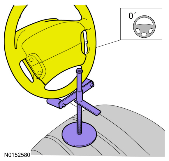
NOTICE: Do not allow the steering column to rotate while the steering column shaft is disconnected or damage to the steering column internal sensor may result.
NOTE: Use a steering wheel holding device (such as Hunter® 28-75-1 or equivalent)
Hold the steering wheel in the straight-ahead position.