Ford Ecosport: Automatic Transmission - 6-Speed Automatic Transmission – 6F35 / Removal and Installation - Main Control Valve Body
Removal
-
Remove the main control cover.
Refer to: Main Control Cover (307-01B Automatic Transmission - 6-Speed
Automatic Transmission – 6F35, Removal and Installation).
-
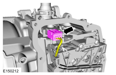
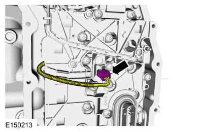
Disconnect the TR sensor electrical connector.
-
Disconnect the OSS sensor electrical connector.
-
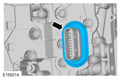
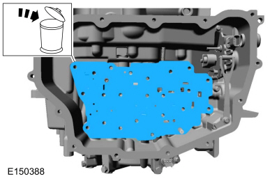
Remove the main control-to-cover seal.
-
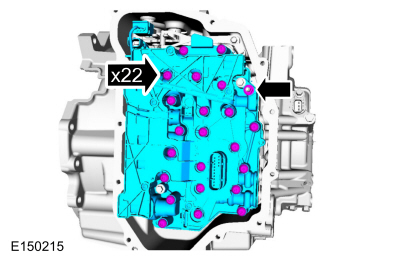
NOTICE:
The main control should be handled with care or damage to the main control may occur .
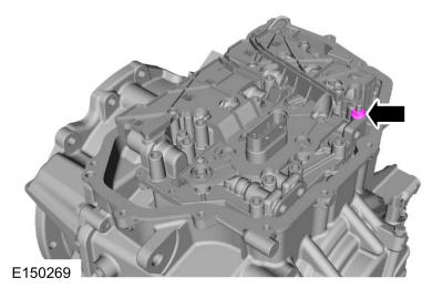
NOTE:
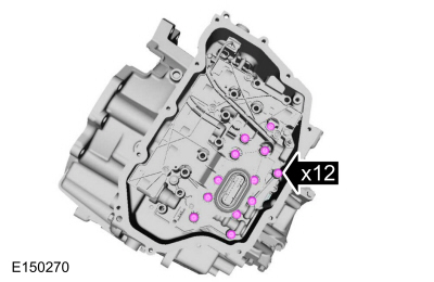
Note the location of the short and long main control-to-transmission case bolts for reassembly.
Remove the main control nut, the main control-to-transmission case bolts and the main control.
-
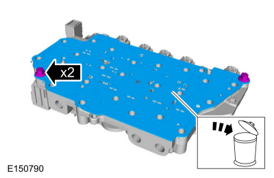
Remove and discard the main control-to-transmission case separator plate.
-
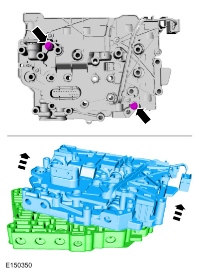
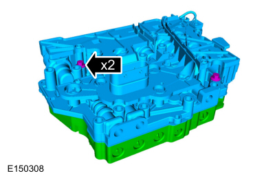
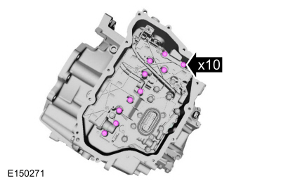
Remove the solenoid body-to-valve body bolts and separate the solenoid body from the main control valve body.
-
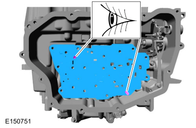
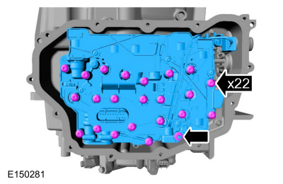
Remove the separator plate-to-solenoid body bolts and remove and discard the separator plate.
Installation
-
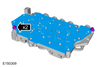
Install the new separator plate and the separator plate-to-solenoid body bolts.
Torque:
89 lb.in (10 Nm)
-
Install the solenoid body onto the main control valve body. Install the solenoid body-to-valve body bolts.
Torque:
89 lb.in (10 Nm)
-
NOTE:
Position the OSS and TR sensor wiring harnesses aside.
Install the new main control-to-transmission case separator plate.
-
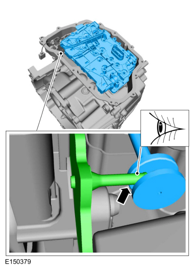
NOTE:
Be sure that the manual lever pin (part of the TR sensor) is correctly installed in the manual valve.
Install the main control assembly.
-
Install the main control nut hand-tight.
-
Install the short main control-to-transmission case bolts hand-tight.
-
Install the long main control-to-transmission case bolts hand-tight.
-
Tighten the main control-to-transmission case bolts and nut in a crisscross pattern.
Torque:
89 lb.in (10 Nm)
-
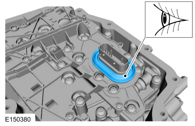
NOTE:
Be sure the main control-to-cover seal is installed with the holes facing up.
Install the main control-to-cover seal.
-
Connect the OSS sensor electrical connector.
-
Connect the TR sensor electrical connector.
-
Install the main control cover.
Refer to: Main Control Cover (307-01B Automatic Transmission - 6-Speed
Automatic Transmission – 6F35, Removal and Installation).
-
NOTE:
The solenoid body strategy data file and solenoid
body identification must be updated anytime a new solenoid body is
installed. A new solenoid body service tag must be installed over the
current solenoid body service tag on top of the transmission case.
If a new solenoid body is installed, the solenoid body strategy will need to be updated.
Refer to: Transmission Strategy Download (307-01B Automatic
Transmission - 6-Speed Automatic Transmission – 6F35, General
Procedures).
Removal
With the vehicle in NEUTRAL, position it on a hoist.
Refer to: Jacking and Lifting - Overview (100-02 Jacking and Lifting, Description and Operation)...
Removal
Remove the main control valve body.
Refer to: Main Control Valve Body (307-01B Automatic Transmission -
6-Speed Automatic Transmission – 6F35, Removal and Installation)...
Other information:
Removal
NOTICE:
Suspension fasteners are critical parts that affect the
performance of vital components and systems. Failure of these fasteners
may result in major service expense. Use the same or equivalent parts if
replacement is necessary...
B00D5:11, B00D5:12 and B00D5:13
Refer to Wiring Diagrams Cell 46 for schematic and connector information.
Normal Operation and Fault Conditions
The RCM briefly activates each LED in the PAD indicator to prove-out
and verify correct functional operation of the PAD indicator to the
occupants...
 Removal and Installation - Main Control Cover
 Removal and Installation - Output Shaft Speed (OSS) Sensor
 205-153
(T80T-4000-W)
205-153
(T80T-4000-W)
 205-990