Ford Ecosport: Fuel Tank and Lines - 2.0L Duratec-HE (129kW/175PS) / Removal and Installation - Fuel Lines
Ford Ecosport 2014-2026 Service and Repair Manual / Fuel System / Fuel Tank and Lines - 2.0L Duratec-HE (129kW/175PS) / Removal and Installation - Fuel Lines
Removal
NOTE: Removal steps in this procedure may contain installation details.
-
With the vehicle in NEUTRAL, position it on a hoist.
Refer to: Jacking and Lifting - Overview (100-02 Jacking and Lifting, Description and Operation).
-
Release the fuel system pressure.
Refer to: Fuel System Pressure Release (310-00C Fuel System - General Information - 2.0L Duratec-HE (129kW/175PS), General Procedures).
-
Disconnect the battery ground cable.
Refer to: Battery Disconnect and Connect (414-01) .
-
If equipped, remove the engine appearance cover.
 |
-
NOTE: Some residual fuel may remain in the fuel lines after releasing the fuel system pressure. When disconnecting or removing any fuel lines, carefully drain any residual fuel into a suitable container.
-
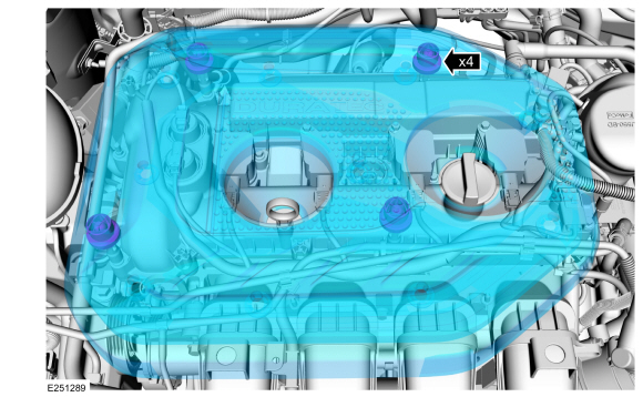
Disconnect the brake lines.
Torque: 133 lb.in (15 Nm)
-
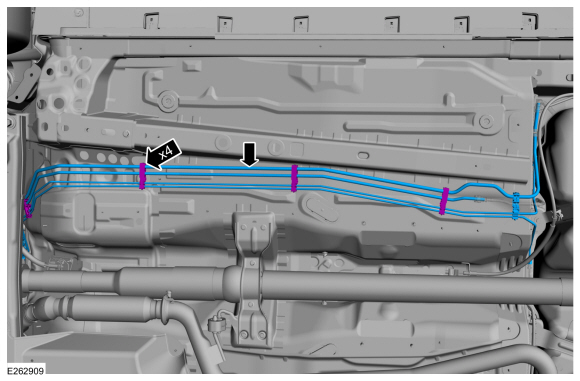
Disconnect the fuel line retainers.
-
Disconnect the quick release couplings.
Refer to: Quick Release Coupling (310-00I) .
-
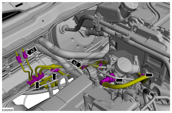
Disconnect the brake lines.
 |
-
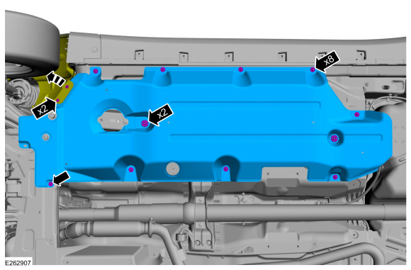
Remove the retainers and the underbody shield.
 |
-
NOTE: Some residual fuel may remain in the fuel lines after releasing the fuel system pressure. When disconnecting or removing any fuel lines, carefully drain any residual fuel into a suitable container.
-
Disconnect the brake tube fittings.
Torque: 133 lb.in (15 Nm)
-
Disconnect the fuel line retainers.
-
Disconnect the quick release couplings.
Refer to: Quick Release Coupling (310-00I) .
-
Disconnect the brake tube fittings.
 |
-
-
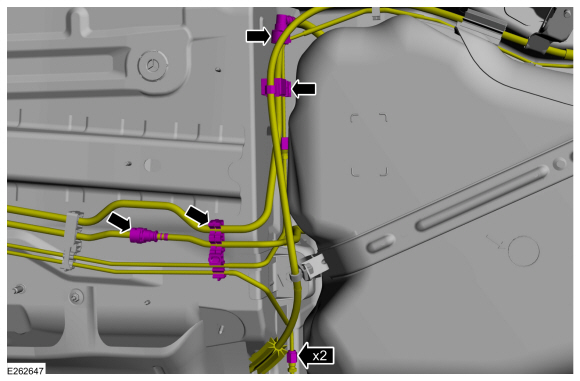
Disconnect the fuel line retainers.
-
Remove the fuel line bundle.
-
Disconnect the fuel line retainers.
 |
Installation
-
To install, reverse the removal procedure.
-
Bleed the brake system.
Refer to: Brake System Pressure Bleeding (206-00) .
 Removal and Installation - Fuel Filter
Removal
NOTE:
Removal steps in this procedure may contain installation details.
Refer to: Fuel System Pressure Release (310-00C Fuel System - General
Information - 2...
 Removal and Installation - Fuel Level Sensor
Removal
NOTE:
Removal steps in this procedure may contain installation details.
Remove the Fuel Pump and Sender Unit.
Refer to: Fuel Pump and Sender Unit (310-01C Fuel Tank and Lines - 2...
Other information:
Ford Ecosport 2014-2026 Service and Repair Manual: Removal and Installation - Steering Column Multifunction Switch RH
Removal NOTE: Removal steps in this procedure may contain installation details. Remove the steering column shrouds. Refer to: Steering Column Shrouds (501-05 Interior Trim and Ornamentation, Removal and Installation). NOTE: Make sure that the component terminals are not bent or damaged...
Ford Ecosport 2014-2026 Service and Repair Manual: Removal and Installation - Rear Wheel Speed Sensor - FWD
Removal NOTE: Removal steps in this procedure may contain installation details. NOTE: Note the position of the rear wheel speed sensor before removal. Remove the wheel and tire. Refer to: Wheel and Tire (204-04A Wheels and Tires, Removal and Installation)...
Categories
- Manuals Home
- 2nd Gen Ford Ecosport Service Manual (2014 - 2026)
- Specifications
- Description and Operation - Evaporative Emissions - System Operation and Component Description
- Removal and Installation - Starter Motor
- Service Information
- Removal and Installation - Evaporative Emission Canister Purge Valve
Removal and Installation - Wheel Knuckle Bushing
Special Tool(s) / General Equipment
Hydraulic PressRemoval
NOTE: Removal steps in this procedure may contain installation details.
Remove the wheel knuckle.Refer to: Wheel Knuckle - Vehicles With: Rear Drum Brakes (204-02B Rear Suspension - AWD, Removal and Installation).
Remove the rear toe adjustment retainers and remove the wheel knuckle mounting bracket.
Torque:
Stage 1: 177 lb.in (20 Nm)
Stage 2: 76 lb.ft (103 Nm)
Copyright © 2026 www.foecosport2.com